
A Samsung Galaxy S4 (and also S5) is a fantastic device to use as a cheap burner phone for one simple reason — a removable battery. It is also well supported with a LineageOS port. Someone gave me an old Samsung Galaxy S4 a few years back that had a damaged display, and I kept it thinking that one day I may need it. A few days ago I decided I wanted to fix that display so I could build a burner phone from scratch with a single messenger app like Session, which has a custom APK file that you can download on to your Android without a Google Play Store or even an F-Droid store. This can be very useful if you do not want Google apps or any other app besides a default browser on your device.
This post outlines how I went about repairing the screen of the S4 first, so that I can have a device that works which is step 1. These devices are really cheap to procure on eBay but nothing is cheaper than free. I will also demonstrate how to disable or remove the selfie camera.
NOTE: Almost all these steps are available on iFixit but nothing beats having your own custom manual.
Step 1: Procure a Samsung Galaxy S4 that has a cracked display.
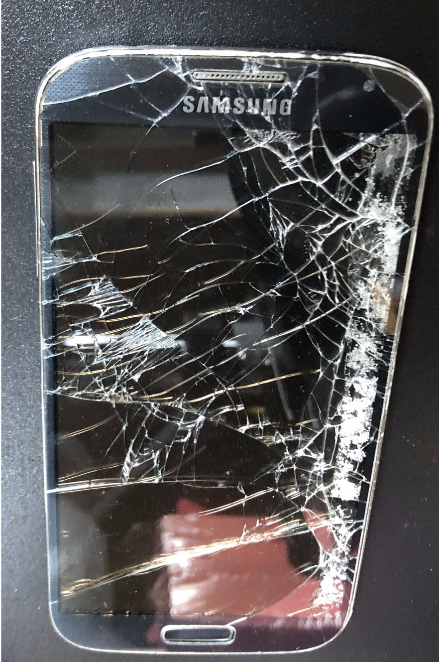 Figure 0. Phone with cracked screen
Step 2: Procure the tools you will need for this process. I used the base electronics kit from iFixit or you can use a cheaper Amazon version of the same. The main thing to have is the
spudger, a screwdriver with #PH-00 bit, tweezers and the trim opening tool.
You must use an anti-static wrist strap (Figure 2) if you have carpeted flooring or if you are wearing woollen clothing.
You will also need the correct model for the replacement display LCD screen. My model number of the device was SCH-I545 and I purchased a screen for that from eBay, or you can get it on Amazon. This model is also called the jfltevzw if you have a Verizon phone or jflte if generic.
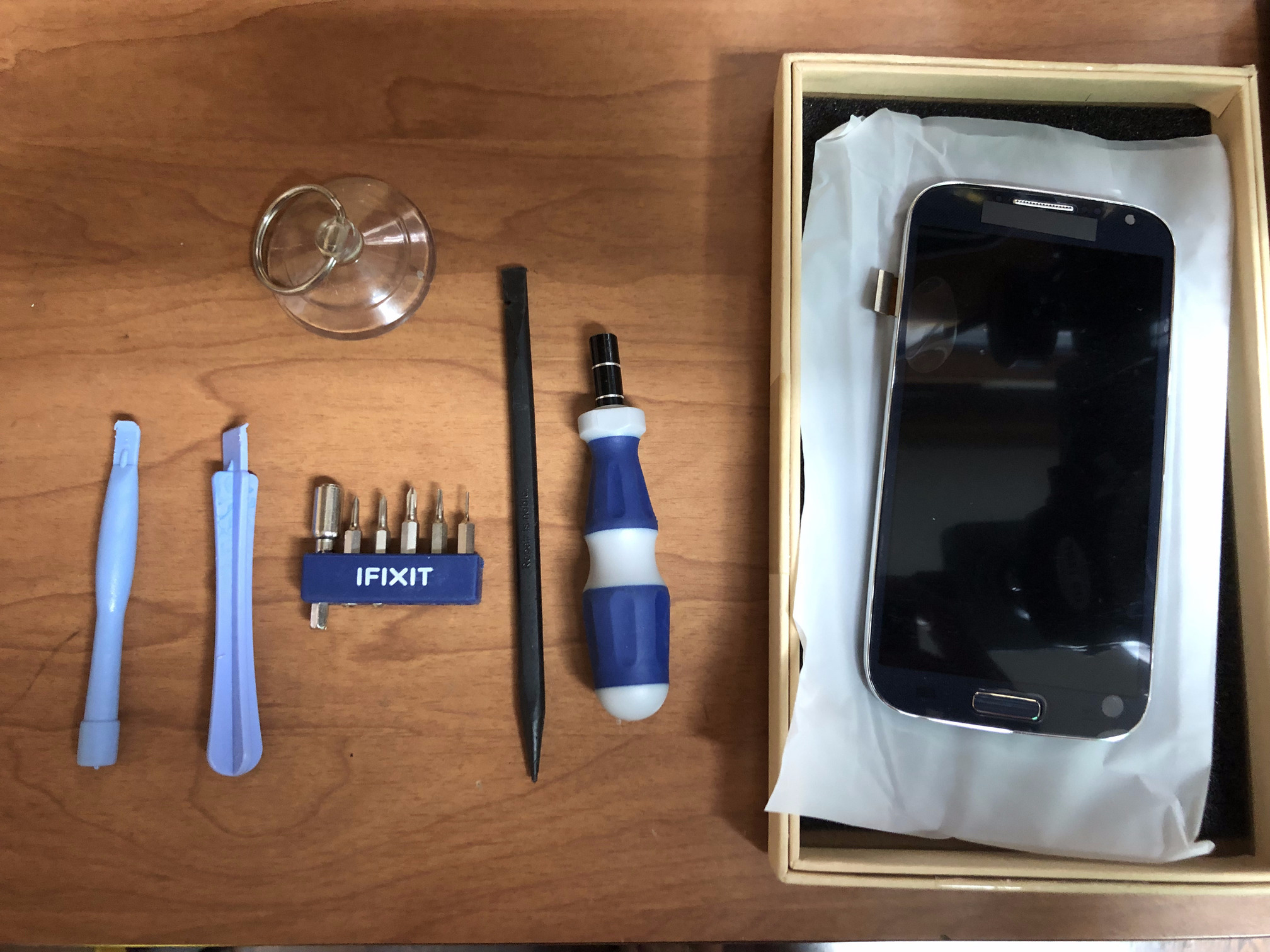 Figure 1. Tools required for this job
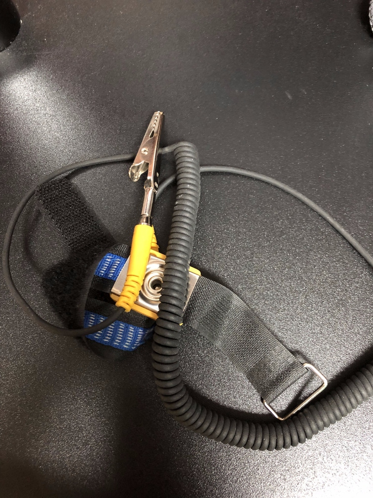 Figure 2. An anti-static wrist strap
Step 3: Remove the back cover of the device to expose the battery. Remove any micro-SD card and SIM cards that may be present in the device and take out the battery.
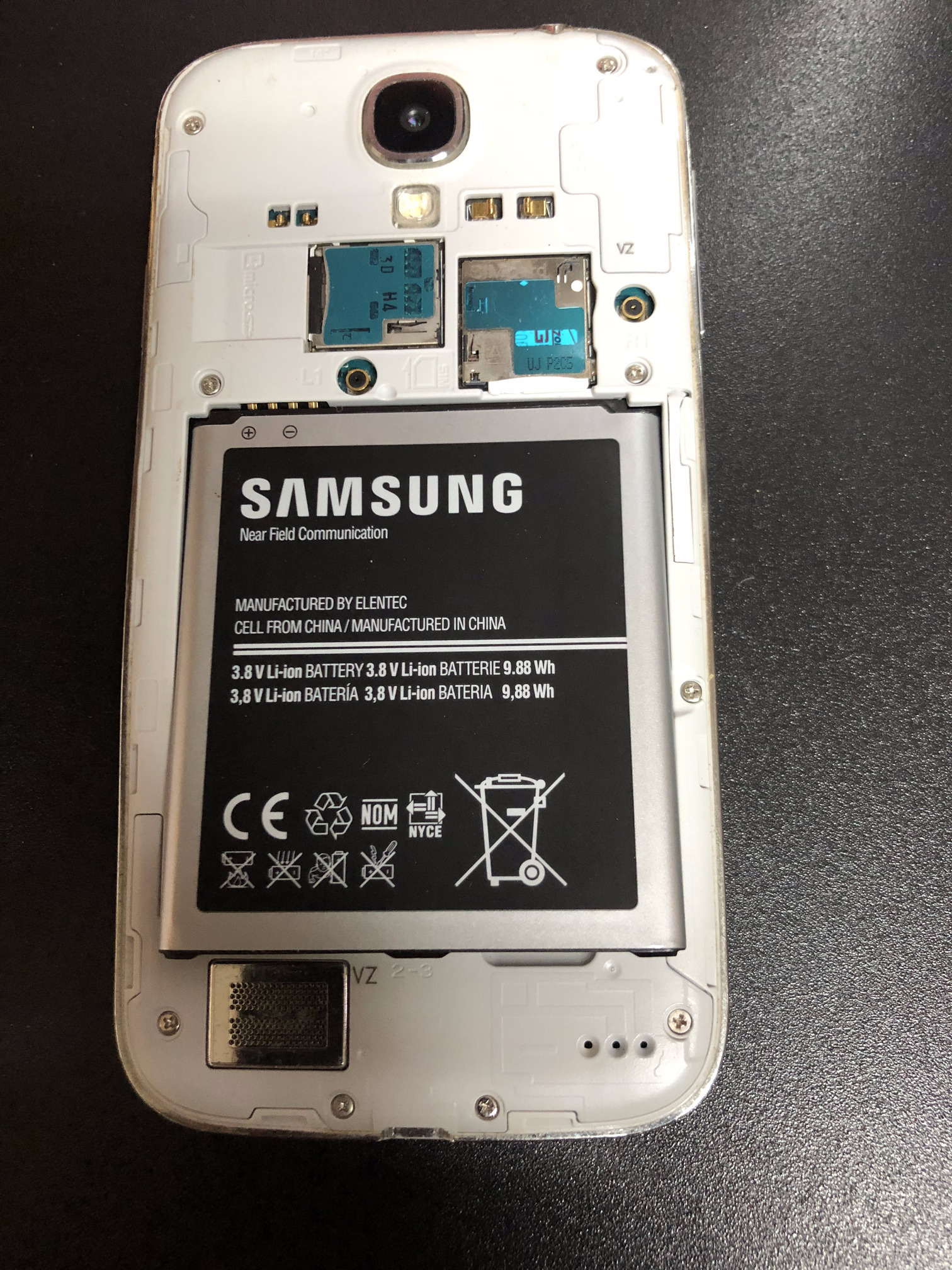 Figure 3. Remove the back cover of the device to expose the battery
Step 4: Using a #PH-00 screwdriver open the 8 screws and keep them aside.
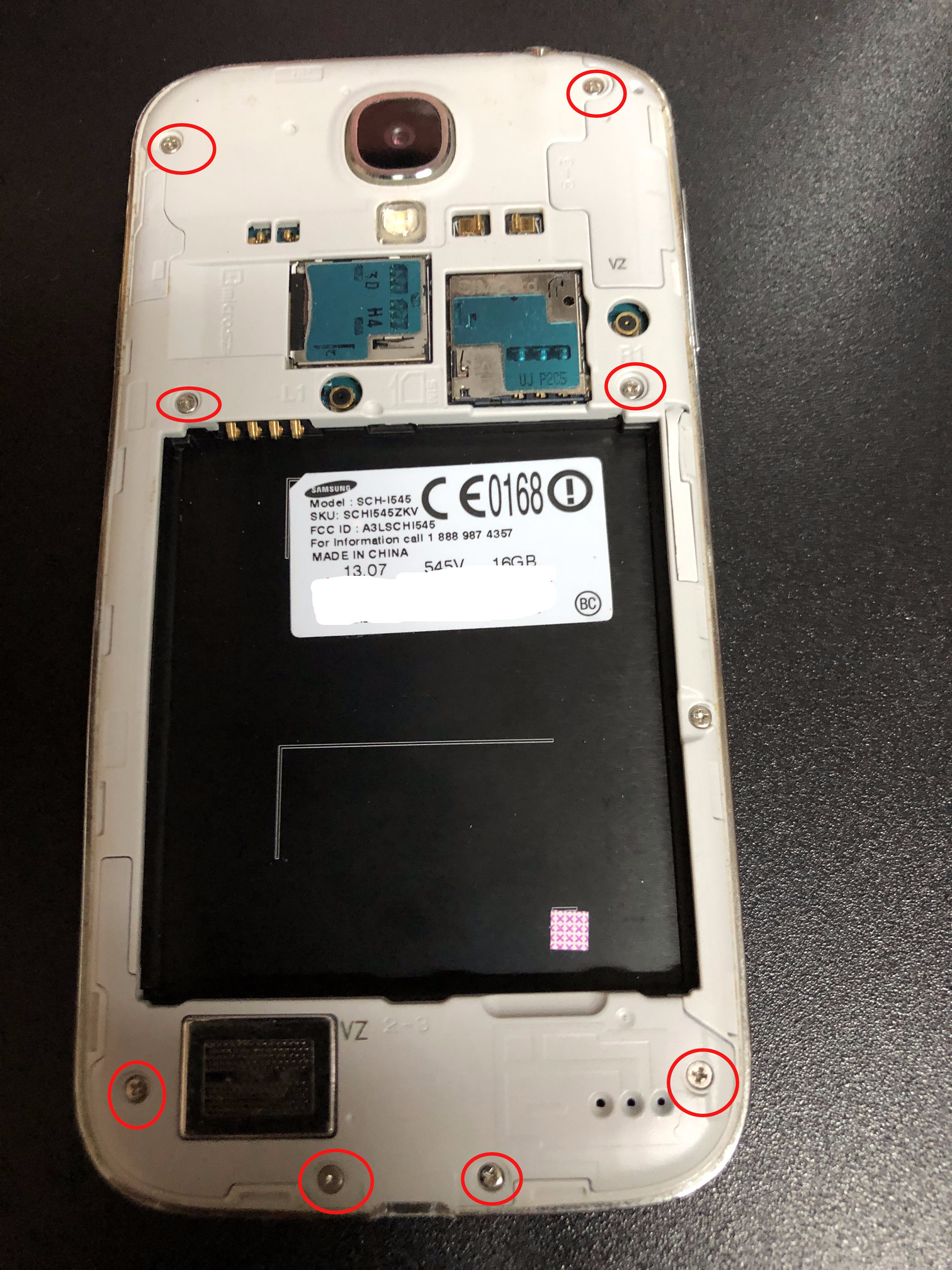 Figure 4. Remove the 8 screws circled in red
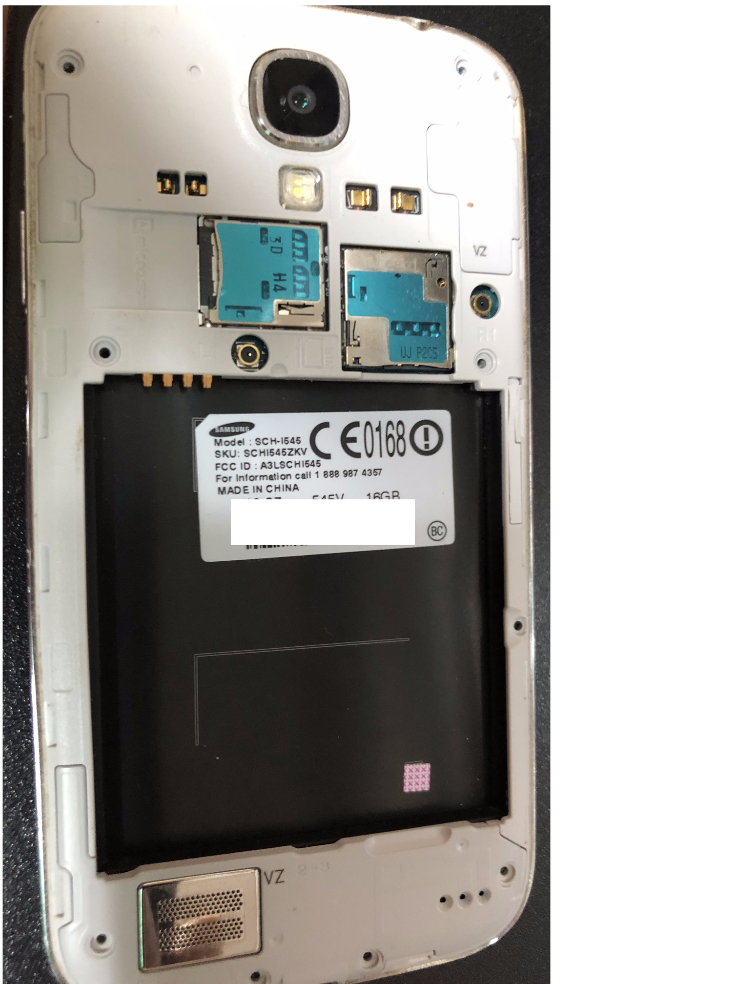 Figure 5. Screws have been removed
Step 5: Now using the blue trim opening tool, start loosening the clips on the greyish white trim by separating it from the front of the device as shown in Figure 6. Figure 7 shows the trim has been removed. Carefully open the trim without breaking any clips. Patience is a virtue !
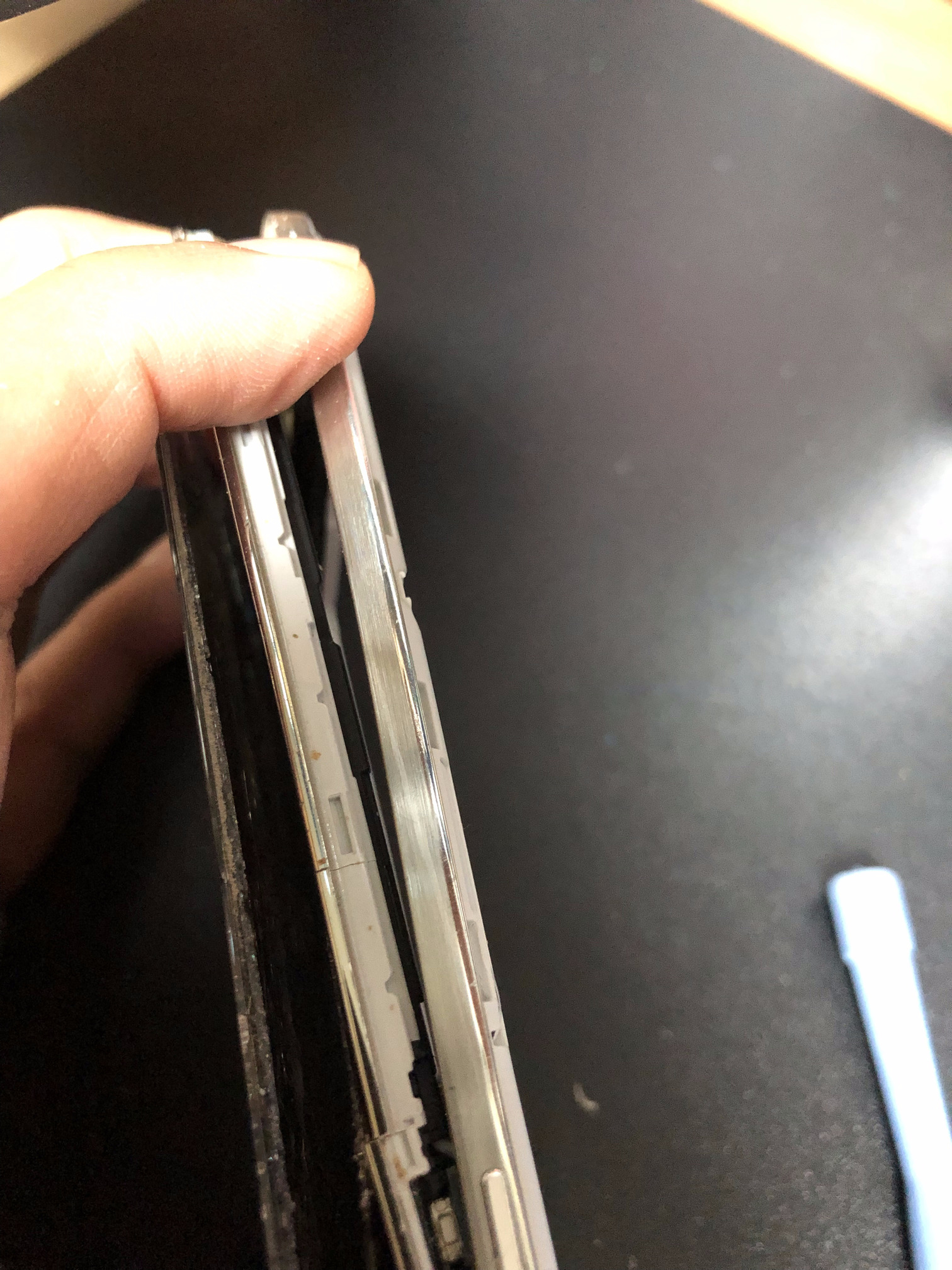 Figure 6. Open the rear trim with the blue trim opening tool
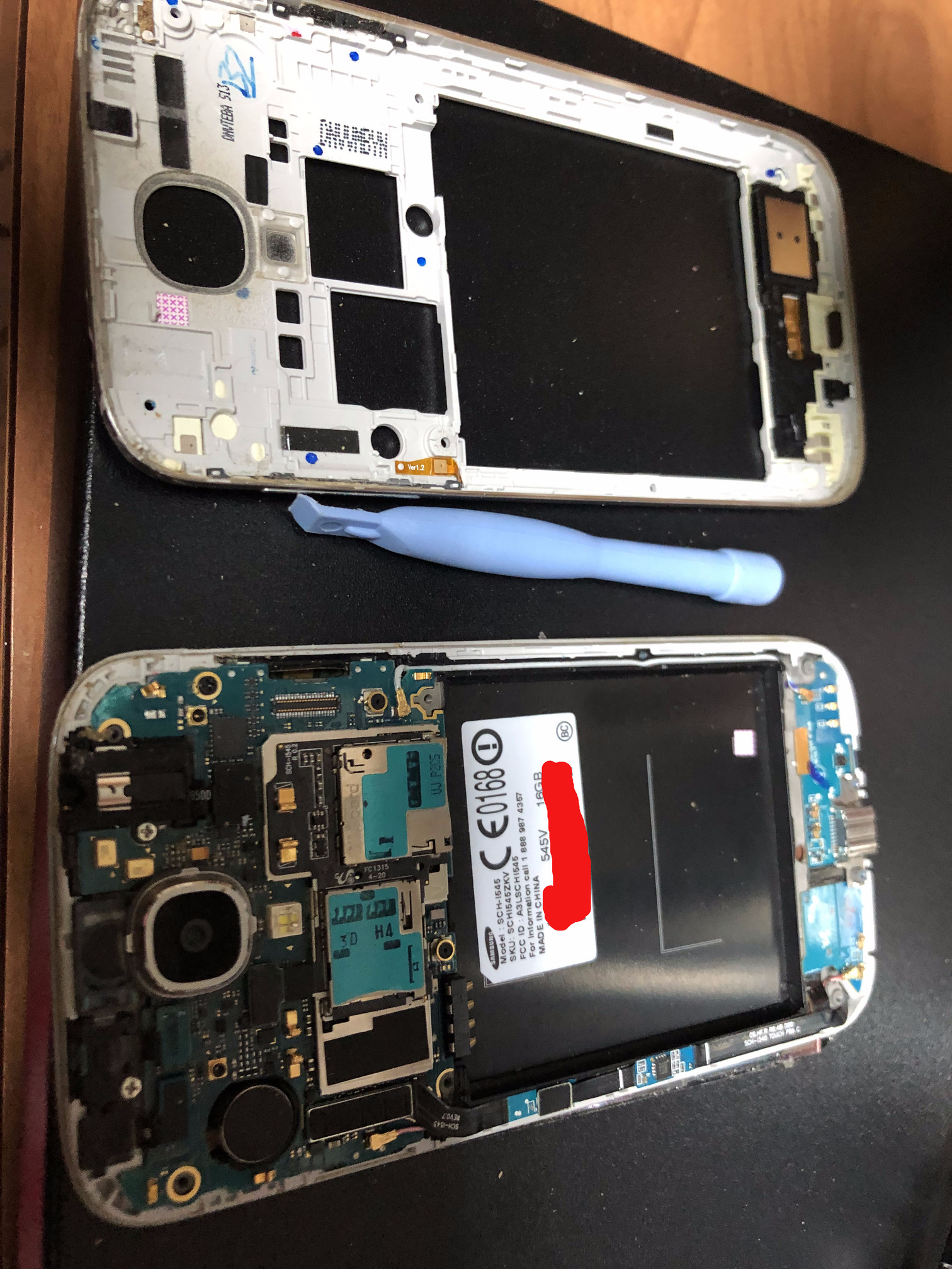 Figure 7. The trim has been removed
Step 6: As seen in Figure 8 with the red circles, using the plastic black spudger or tweezers, detach the various clips from the motherboard. You will be detaching the clips for the USB charging module, selfie camera, speaker, headphone jack, the display LCD (yellow circle), the mobile antenna and home button μSMA connectors, and two other screws that hold the headphone jack and motherboard to the display LCD. Figure 9 shows the result of the clips being detached.
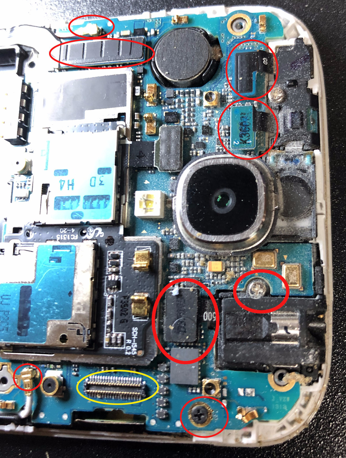 Figure 8. Open the clips and remove the screws to free up the motherboard
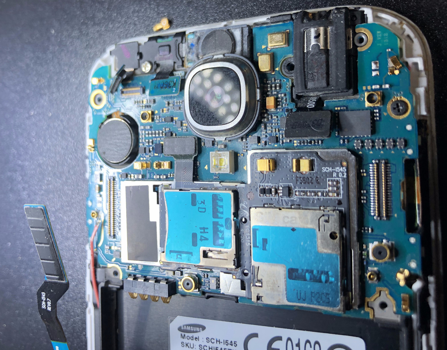 Figure 9. Clips have been detached from the motherboard
Step 7: Carefully lift up the motherboard out of the device and keep it aside. Now you need to open the screw shown by the red circle in Figure 10. This will enable you to remove the selfie camera and speaker.
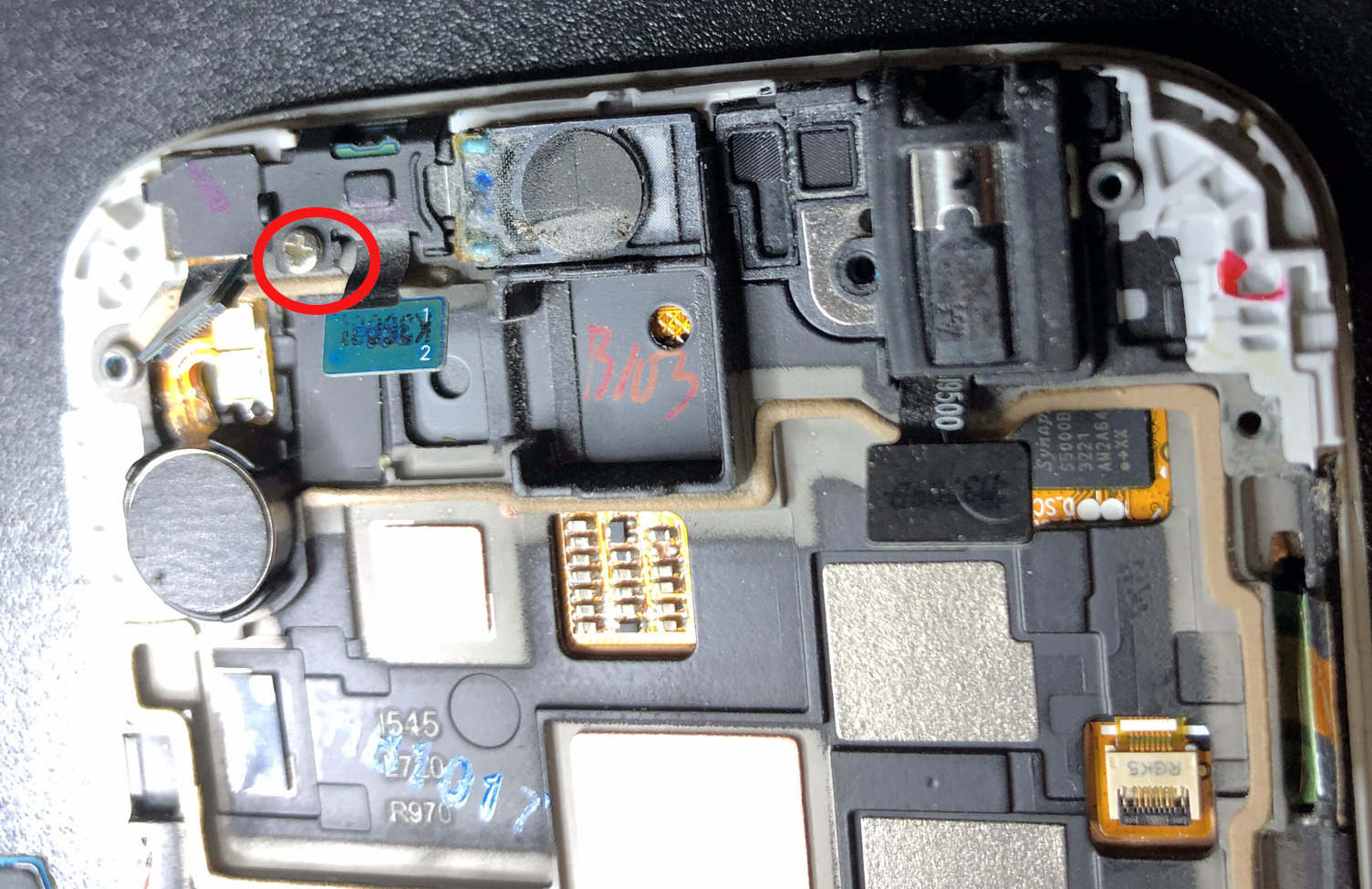 Figure 10. Motherboard has been removed. Notice the screw that needs to be taken out
Step 8: Once the screw has been removed, using the spudger or a tweezer lift the metallic (or plastic) boot out of its position as shown in Figure 11.
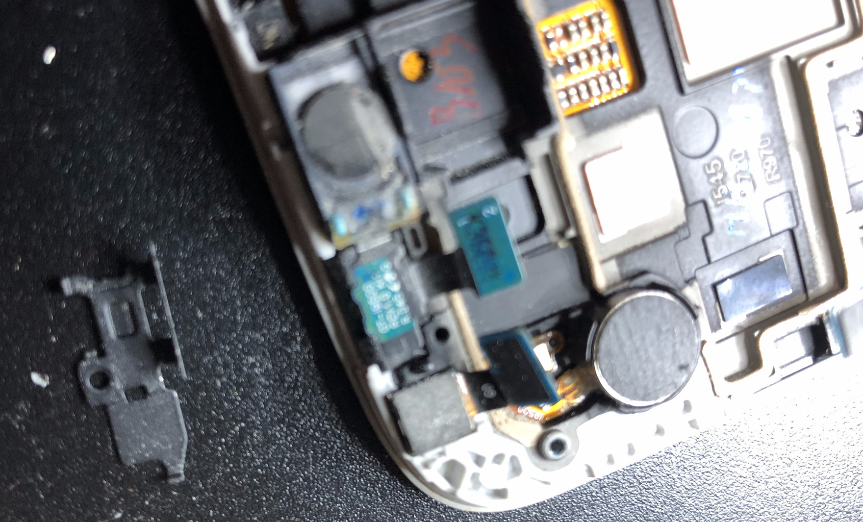 Figure 11. Remove the protective boot or cover off the speaker and selfie camera
Step 9: Now take out the selfie camera with a tweezer. If you are serious about making a burner phone, you would not install a selfie camera back in place. In my case, the camera was already damaged as the ribbon was slit. So it was a non-functioning camera anyway, which is why I put it back in place but after cutting out the ribbon completely as shown in Figure 12b.
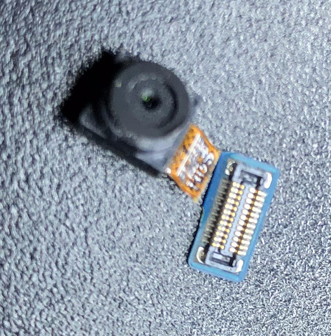 Figure 12a. Damaged selfie or front facing camera
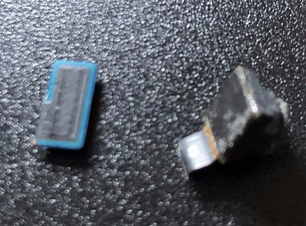 Figure 12b. Camera connection Ribbon has been cut
Step 10: Now remove the speaker assembly as shown in figure 13. If you want your burner phone to only have text messaging capabilities, I would not put the speaker back in place either, since you will never need to listen to anything unless you are expecting audio/video messages. You can detect the arrival of messages just by keeping the device in vibrate mode, if all you want is text messages. Even then, you could technically listen to audio/video messages using the headphone jack.
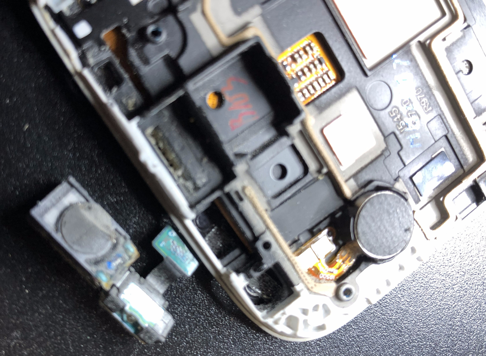 Figure 13. Remove the speaker assembly
Step 11: Using a heat gun heat the vibrate motor (black circular piece in Figure 14) till the spudger can delicately move it out of position as seen in Figure 15. This can take about 1 or 2 minutes on low heat. Lift it out while maintaining the adhesive on the motor itself, so that it can be reused later (Figure 16).
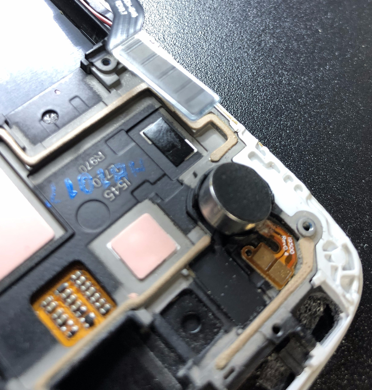 Figure 14. Using a heat gun heat the vibrate motor
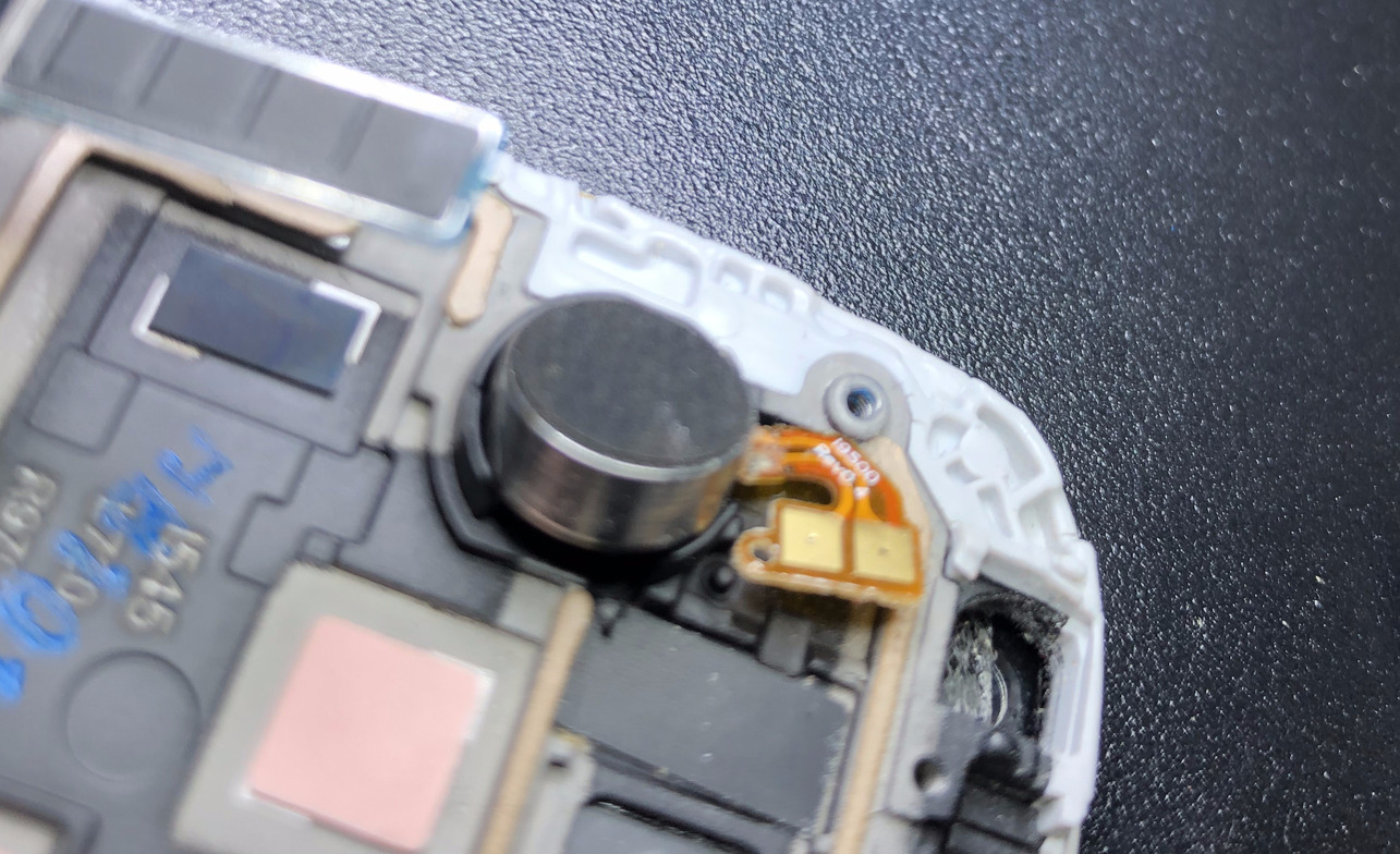 Figure 15. Lift the motor out of its position
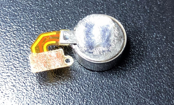 Figure 16. Vibrate motor has been removed. Notice the adhesive on the motor is intact
Step 12: Next we remove the home button cable connecting the motherboard to the USB charging module. We had removed the μSMA connector earlier from the motherboard in Step 6. Now we remove a μSMA connector from the USB charging module too and pull it out safely without breaking it. If you break it, you have to replace the whole cable! You cannot solder your way out of it unless you have a μSMA crimping tool.
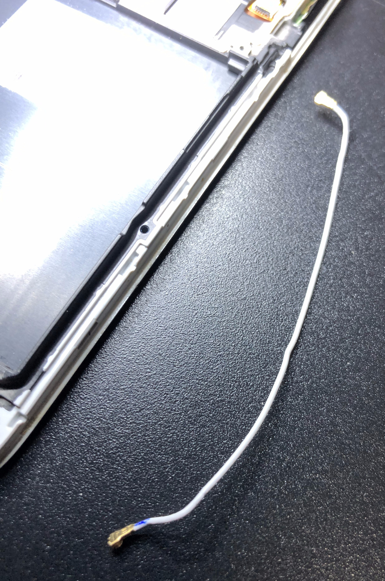 Figure 17. Remove the home button cable
Step 13: We need to remove the USB charging module which is glued on to the base of the display. To do this first remove the USB charging port cover using a spudger. It may require some effort but be gentle. We need to reuse all of these parts, so try not to break them.
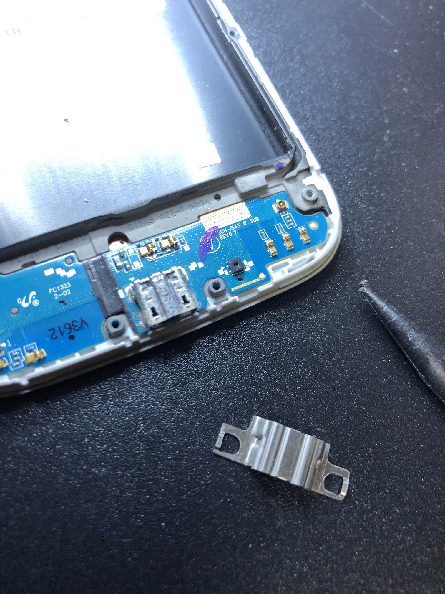 Figure 18. Remove the USB charging port cover using a spudger
Step 14: Since our device is a Verizon CDMA version of the Samsung Galaxy S4, it has a pink μSMA connector cable connecting the antenna to the USB charging module as shown by the red circle in Figure 19. Unfortunately, the other end of the cable got damaged while removing it so in my case the phone feature will not work on this burner phone and may be a good thing. However, that means the device will need to rely on WiFi for internet access. That has its own disadvantages in rural areas with poor free WiFi availability, but may be great for cities. It is even better for use in protests since you will not be caught up in dragnets setup by law enforcement or other adversaries, where they use cell site simulators and force your device to connect to their malicious network. However, you will need to connect to a WiFi network at that point which is easier to do in cities due to free coffee shop WiFi availability.
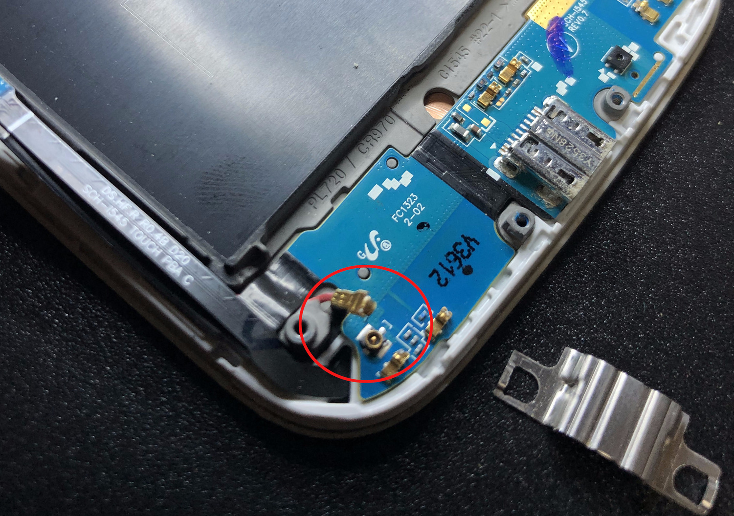 Figure 19. Detach antenna cable connector
Step 15: Using a heat gun again lightly heat up the whole USB charging module and start lifting it out of its place using a spudger. Start from the left of the charging module (Figure 20) and you should find success as you can see in Figure 21. If your USB charging port is damaged, this would be the time to replace it with a new USB charging module.
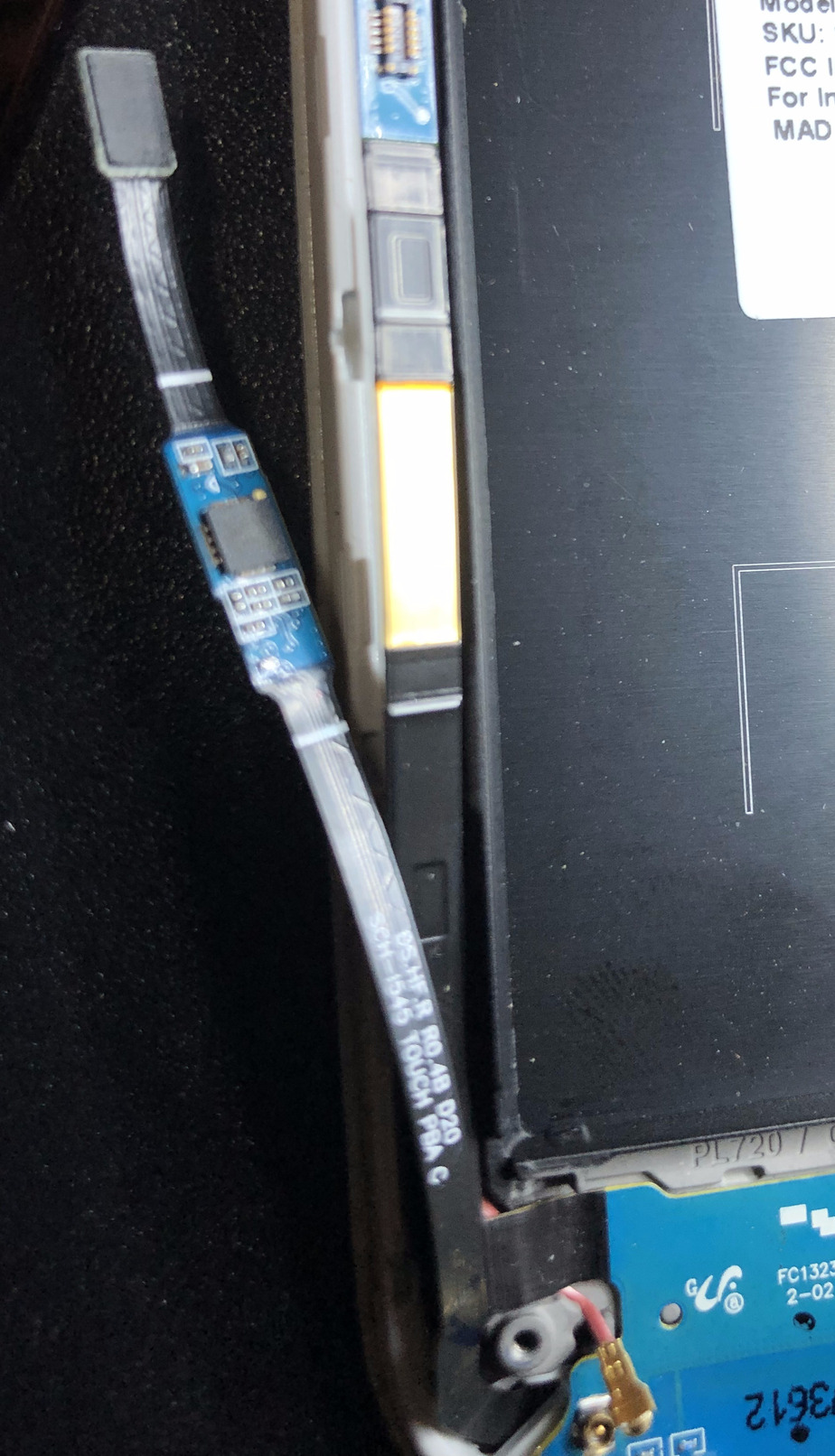 Figure 20. Using a heat gun start heating the left of the USB charging module
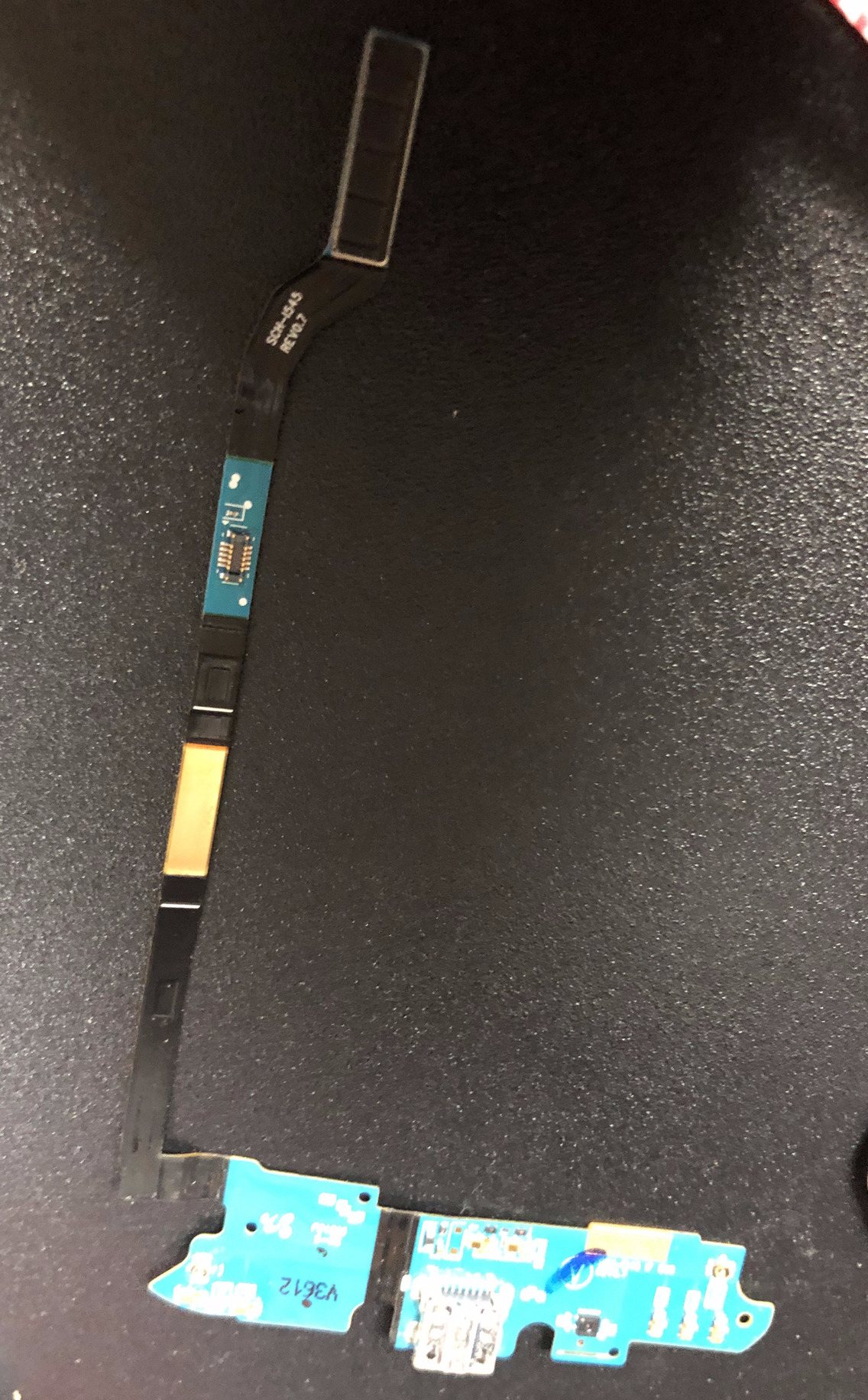 Figure 21. USB charging module removed
Step 16: Now take out the new display module you procured from eBay in Step 1 from its packaging. It should look like Figure 22. Note that the display module includes both the LCD module and the glass that protects the module.
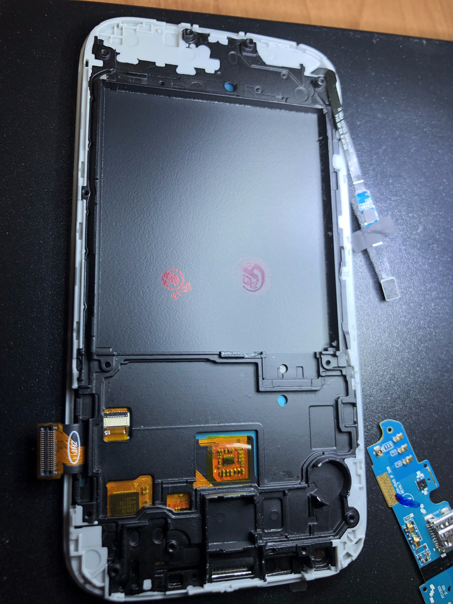 Figure 22. New display module
NOTE: This is where we document the rest of the process of installing the display and bringing the device back to near new condition, which the iFixit modules don’t always describe.
Step 17: Install the USB charging module back in place and using a heat gun melt the adhesive and lightly press the module in place.
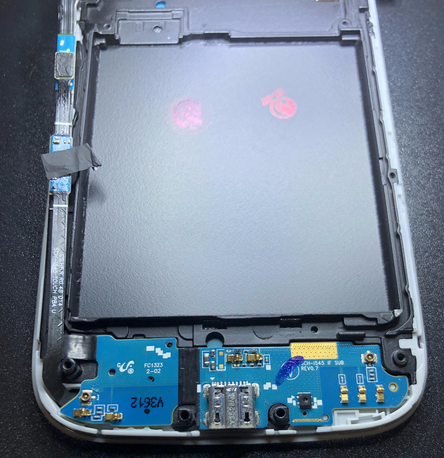 Figure 23. USB charging module installed
Step 18: Install the USB charging port clip back into place (Figure 24) and using a spudger make sure that the clip fits tightly enough. In my case, it was loose but good enough.
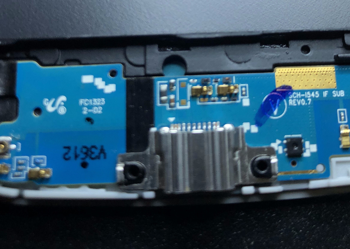 Figure 24. Install the USB charging port clip
Step 19: Place the speaker back in place (Figure 25) and optionally place the selfie camera back in place (Figure 26). In my case, since I had cut out the selfie camera ribbon connector (Figure 12b), I placed it back in place to allow for the device to close nicely and also to appear to have a camera.
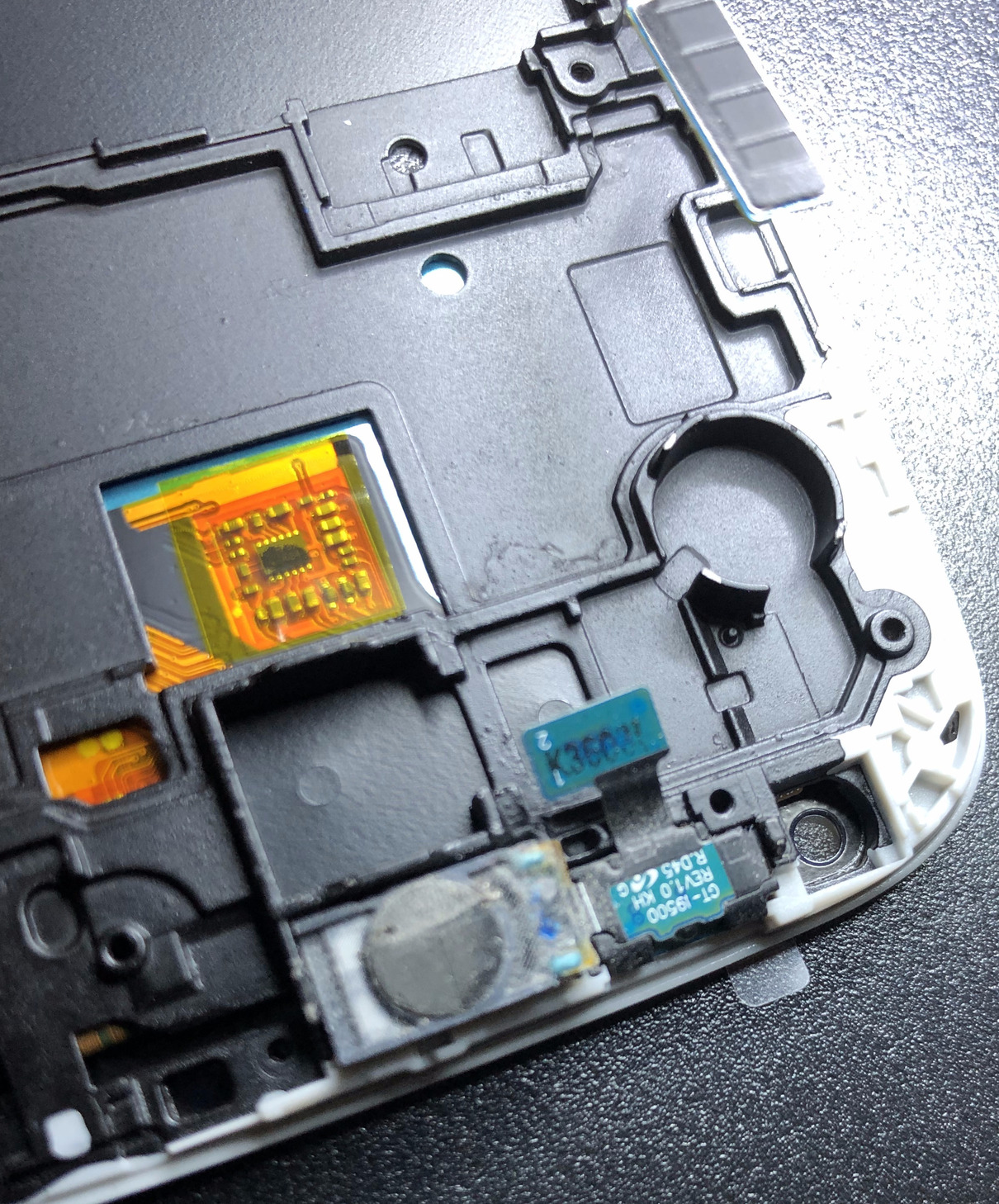 Figure 25. Place speaker back in position
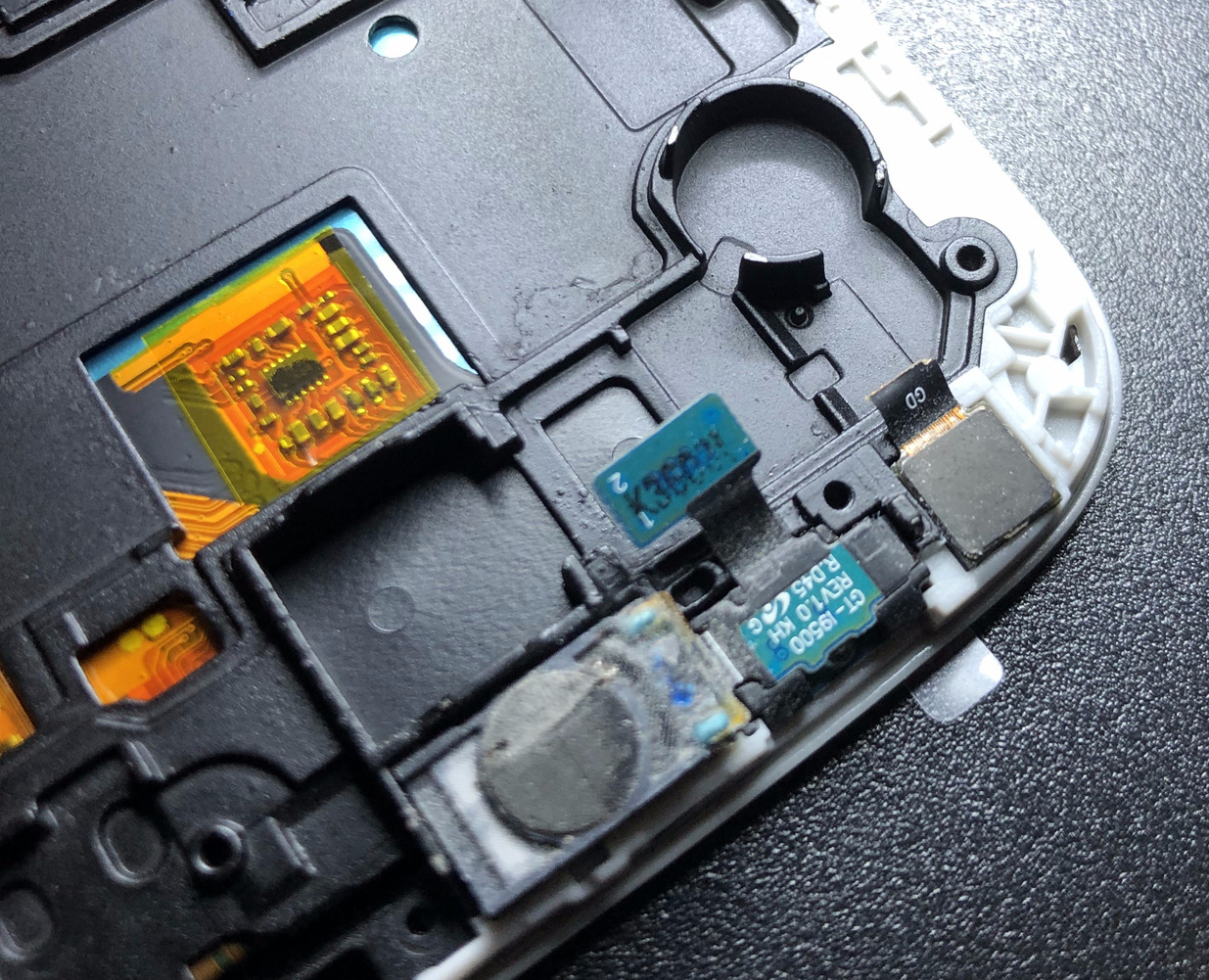 Figure 26. Place selfie camera back in position
Step 20: Screw the protective boot back into place that you had removed in Step 11.
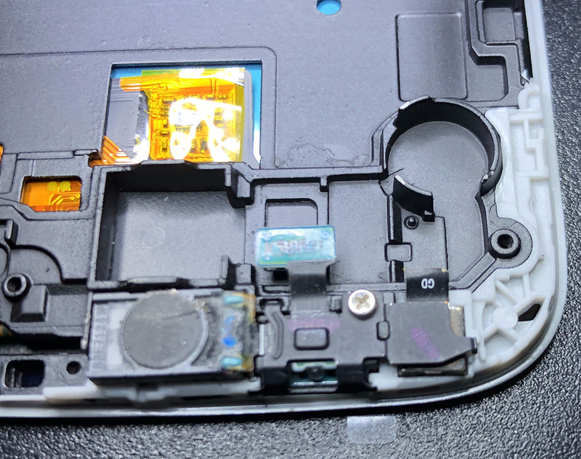 Figure 27. Screw the protective boot back in place
Step 21: Place the vibrate motor back in position and using a heat gun melt the adhesive and push it down so it sticks.
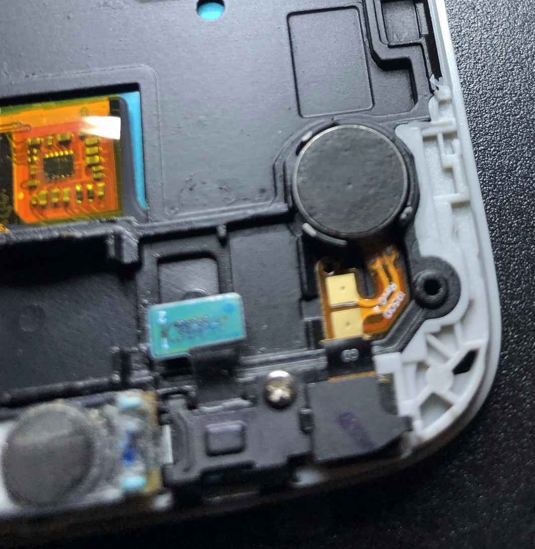 Figure 28. Place the vibrate motor in position and heat the adhesive
Step 22: Now install the headphone jack back in place along with its screw.
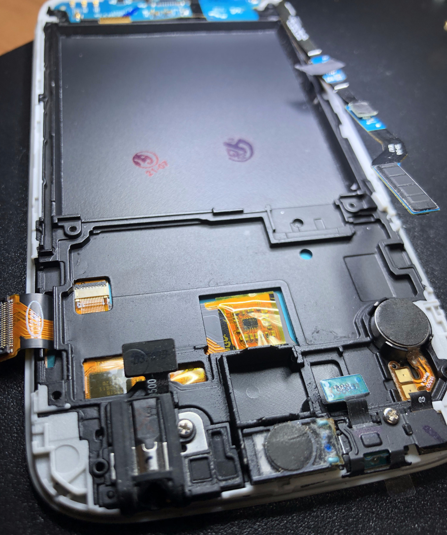 Figure 29. Screw the headphone jack back in place
Step 23: Connect the μSMA connector of one end of the home button cable, removed in Step 12, to the USB charging module first. Run the rest of the cable along the side of the display carefully.
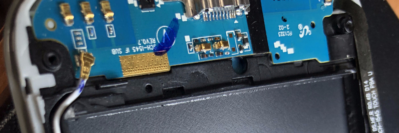 Figure 30. Connect home button cable to USB charging module
Step 24: Install the motherboard in place (Figure 31) and make sure all the clips and μSMA connectors are above the motherboard. Then clip them in place as shown in Figure 32. Do not forget to install the black screw to hold the motherboard to the display frame. I do not recommend removing the rear facing camera since that can be useful for a burner phone, unlike a front facing or selfie camera which can leak info of the device user, if turned on remotely by a malicious entity. For my broken selfie camera, I installed the broken clip into its socket even though it is not attached to the camera itself.
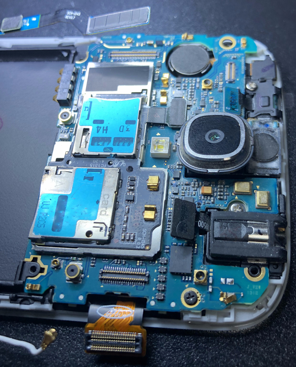 Figure 31. Install the motherboard and screw it to the display frame using the black screw
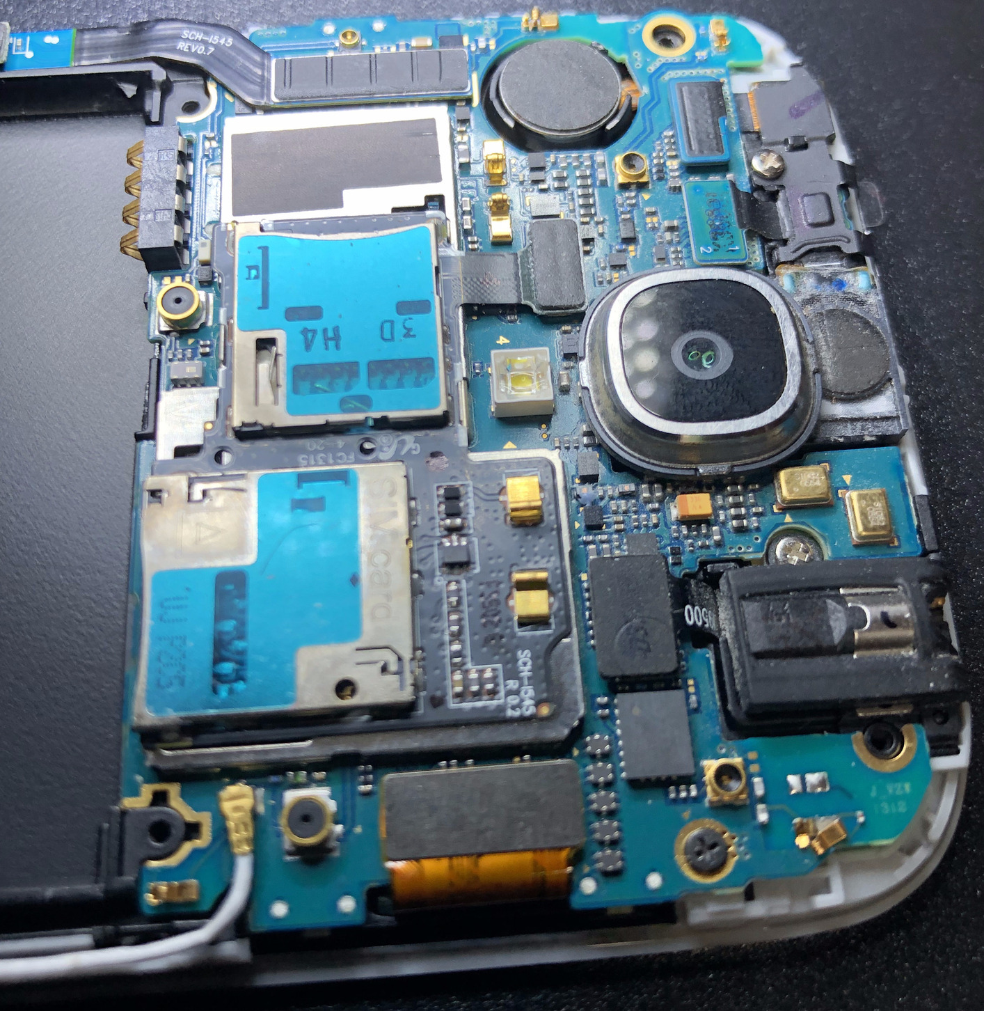 Figure 32. Clip all the accessories back into their sockets
Step 25: Now connect the battery to the device as shown in Figure 33 and test that it boots up by pressing the power button to turn on the device. As seen in Figure 34, I can now see the Samsung logo when the device starts. So at least we now know that the motherboard has been connected correctly.
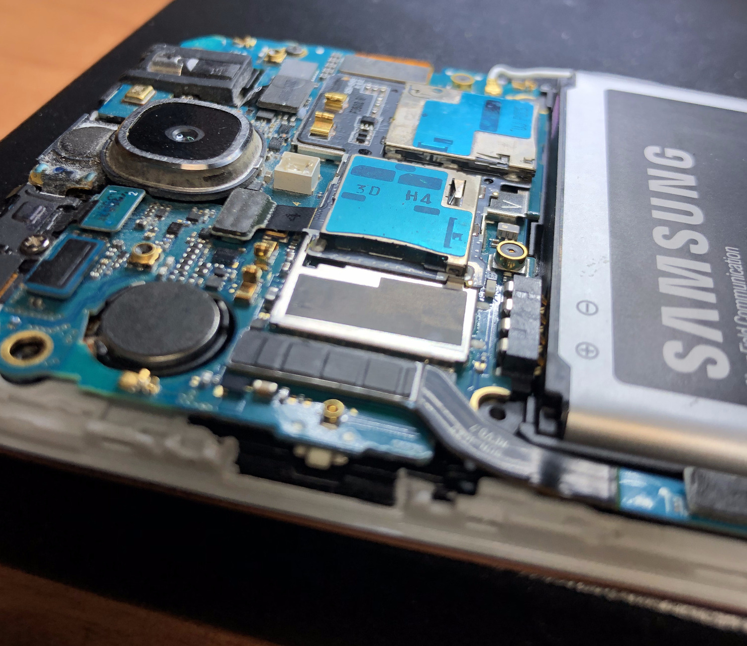 Figure 33. Connect the battery
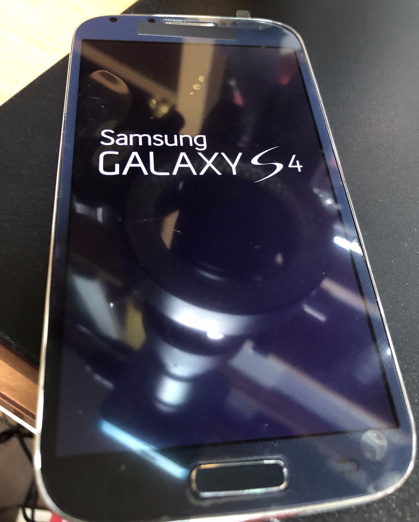 Figure 34. Phone boots up
Step 26: Now take out the battery again. Re-install the back trim cover that you had removed in Step 5. Remember to screw it back to the rest of the device body using the 8 screws that were removed earlier. Install the battery back in place as shown in Figure 35.
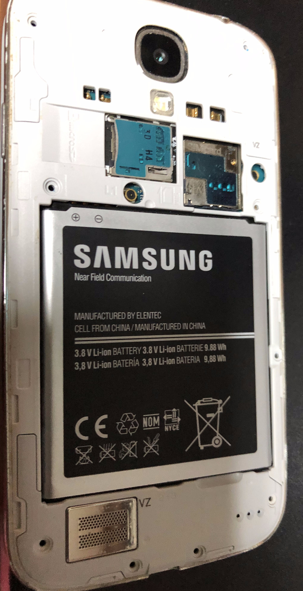 Figure 35. Re-install the back trim cover
Step 27: Press the power button and boot the phone all the way until it starts loading the operating system. Figure 36 shows us that the phone has the Verizon splash screen and Figure 37 shows the Android operating system boot up. Next to it is the damaged display module.
 Figure 36. Boot the phone into the operating system
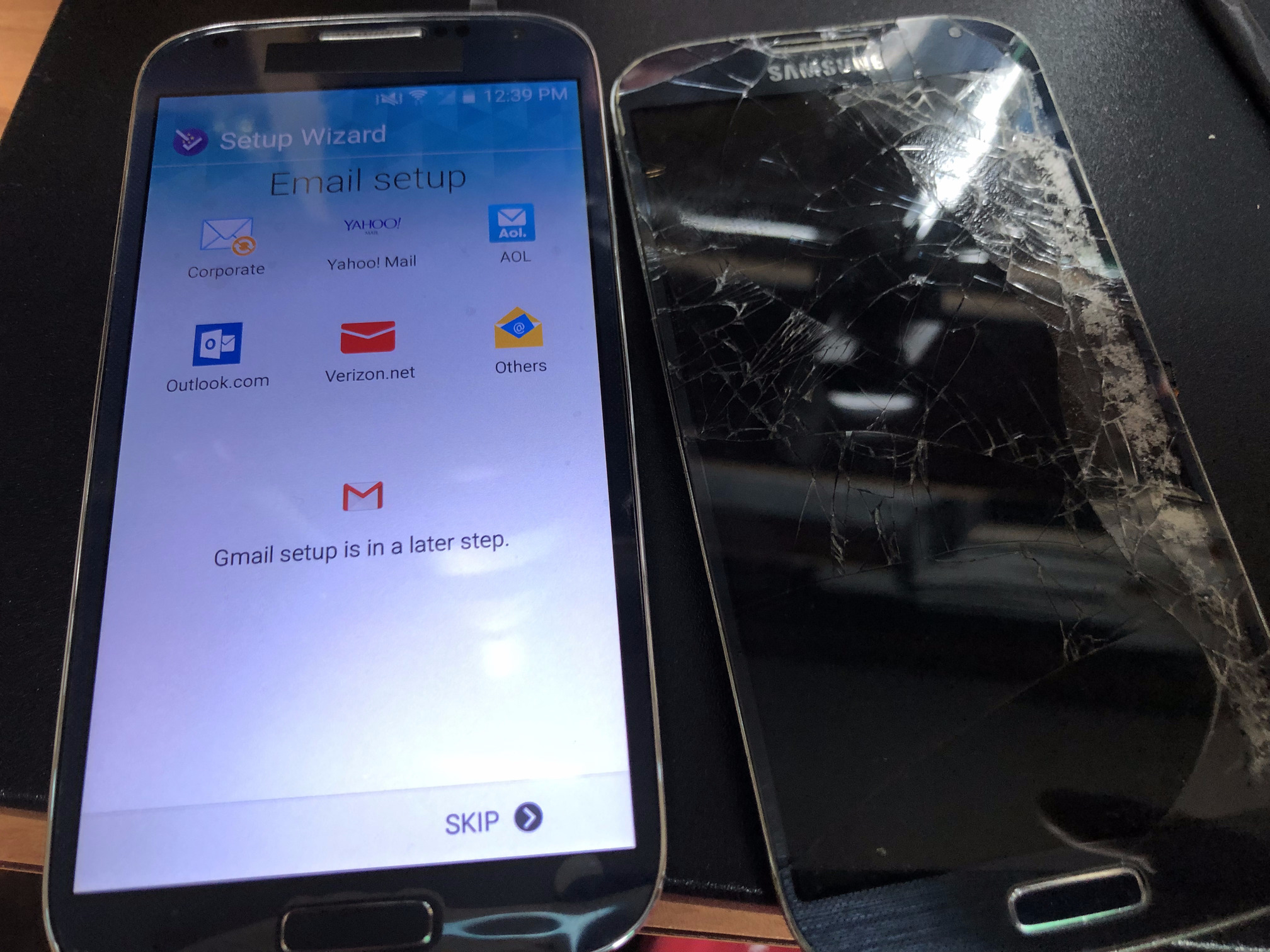 Figure 37. Working phone with new display module. Also seen is the damaged display module
Step 28: Now connect the device to your computer using a USB cable. Turn on Android USB debugging by following instructions. You should then be able to see this device listed under the Android Debug Bridge (adb).
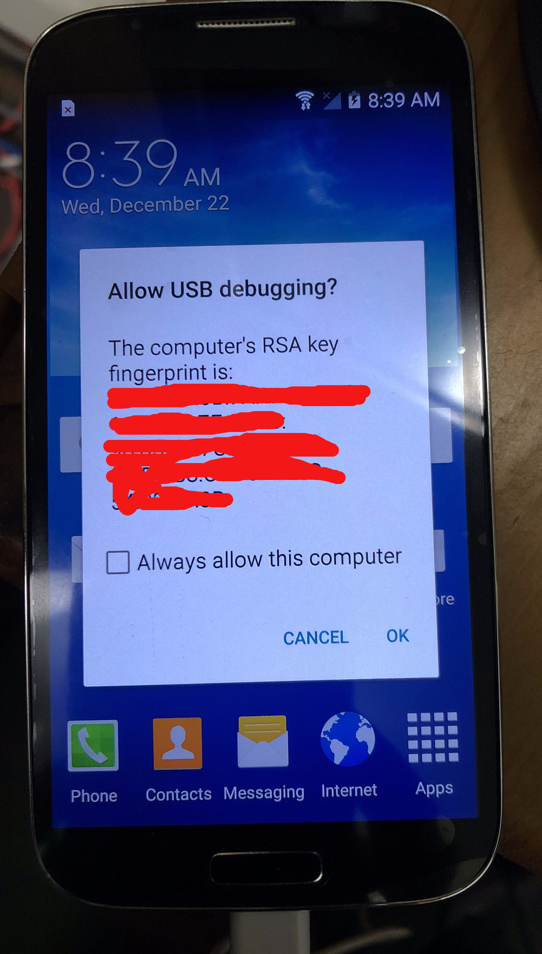 Figure 38. USB debugging is enabled
Next step would be to root the phone by installing a custom bootloader called TWRP, by compiling it from scratch, which is going to be described in a future blog post. Once the phone is rooted, you can then install a LineageOS ROM on to the device without Google tracking. Following that you can install the Session App.
 Donate BITCOIN to 19hrWWw1dPvBE1wVPfCnH8LqnUwsT3NsHW.