Electronics is getting tinier and my eyes are getting older. To be able to re-use old hardware, sometimes it is necessary to:
- discover the JTAG, SPI, I2C or UART pins on the circuit board, or
- extract and/or reload firmware correctly without damaging the board, or
- check the quality of the connnections of the main processor chips, or
- map the pins of the main processor back to a datasheet, especially with custom ASICs and System-on-Chips (SoCs) being made based on standard designs but by arbitrary vendors.
I saw this post on Twitter, got excited and ordered a full microscope which could do 300X zoom from AliExpress. This took a month to arrive, but was an exciting wait.
The microscope and the stand arrived last Friday, and I assembled it myself. However, it does not have an assembly manual so this post will act as one.
Since this post is really long, the Table of Contents below can allow the reader to skip to the appropriate section of interest.
TABLE OF CONTENTS
- 1. Original Informative Post
- 2. Purchasing the Microscope
- 3. Assembling the Stand
- 4. Setting Up the Microscope
- 5. Using the Microscope
- 6. Vendor Specification Images
Original Informative Post
So I went to Ali (as usual) and bought this one: 38MP, 1080p@60Hz camera with HDMI output, coupled with 20-180x optics. Whole kit went for ~$200 delivered. pic.twitter.com/GU9HflQqxp
— Andrey Ø. (@rombik_su) October 4, 2020
Purchasing the Microscope
I purchased the microscope from the Eakins Store on AliExpress with:
- 30-300X zoom,
- 1080p@60Hz 38MP camera,
- HDMI and USB output,
- a micro-SD card slot, and
- an electric LED light attachment.
It cost nearly $179 with taxes and free delivery from AliExpress. It took a month to arrive. Looks like it was shipped in bulk with a bunch of other items via flight, cleared customs in both China and USA, and then using a local re-shipper was shipped to me.
The microscope stand additionally cost $47 but the shipping to the US was $54 via DHL and arrived in a week. Despite these being sent by the same store, I ended up buying them separately rather than as a kit.
A TV or monitor with HDMI input is necessary to test the microscope. I have used a 21” $90 TV from Best Buy that I had purchased a few years ago.
Assembling the Stand
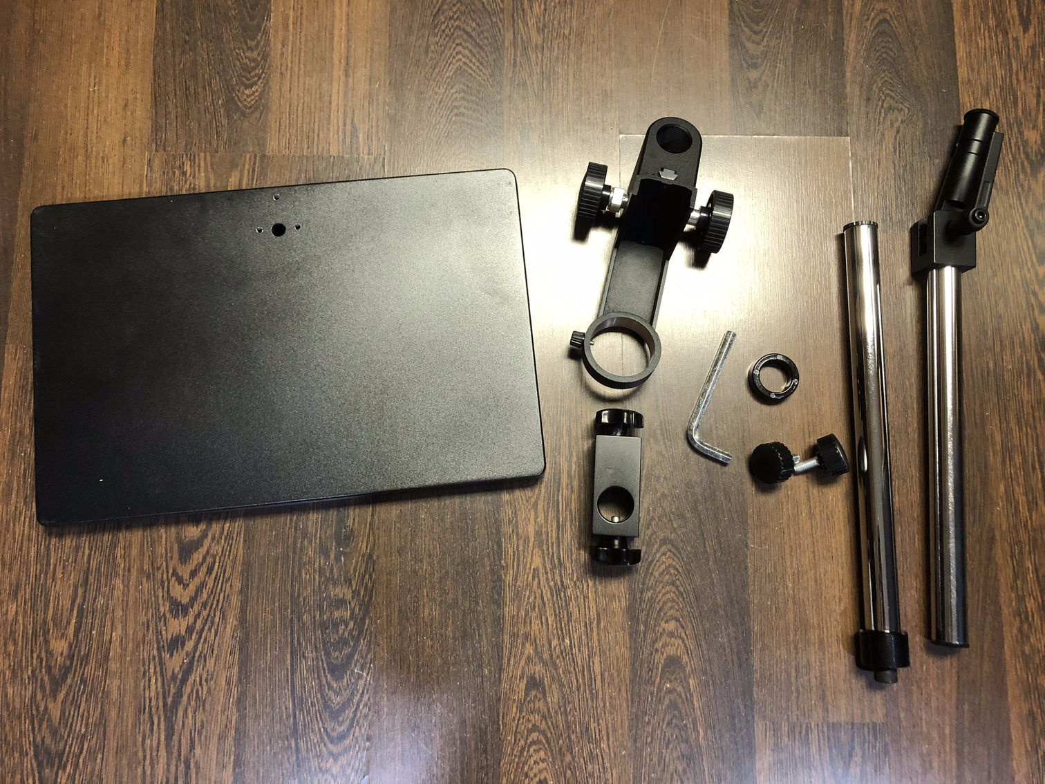
The stand requires assembly and all the components are shown in the image for Step 1. However, it does not come with an assembly manual. Therefore, to make it easier for anyone who is planning on buying this microscope and stand, I have decided to write a simple manual in this post.
Step 1: Unbox all the components of the stand.
Step 2: Unscrew the nut on the main pillar rod of the stand using the supplied hex key.
Step 3: Flip the base, so that the pillar rod can be screwed to the hole in the base using the nut and the supplied hex key.

Step 4: Screw the pillar rod to the base using the nut and the hex key.
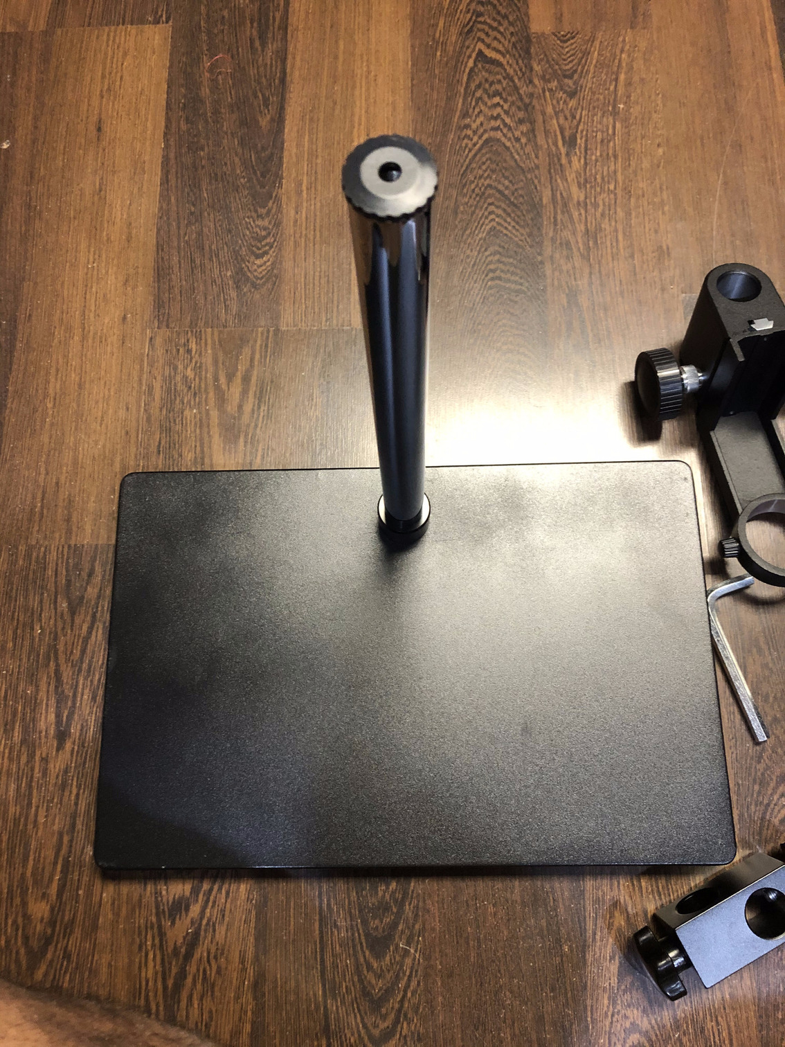
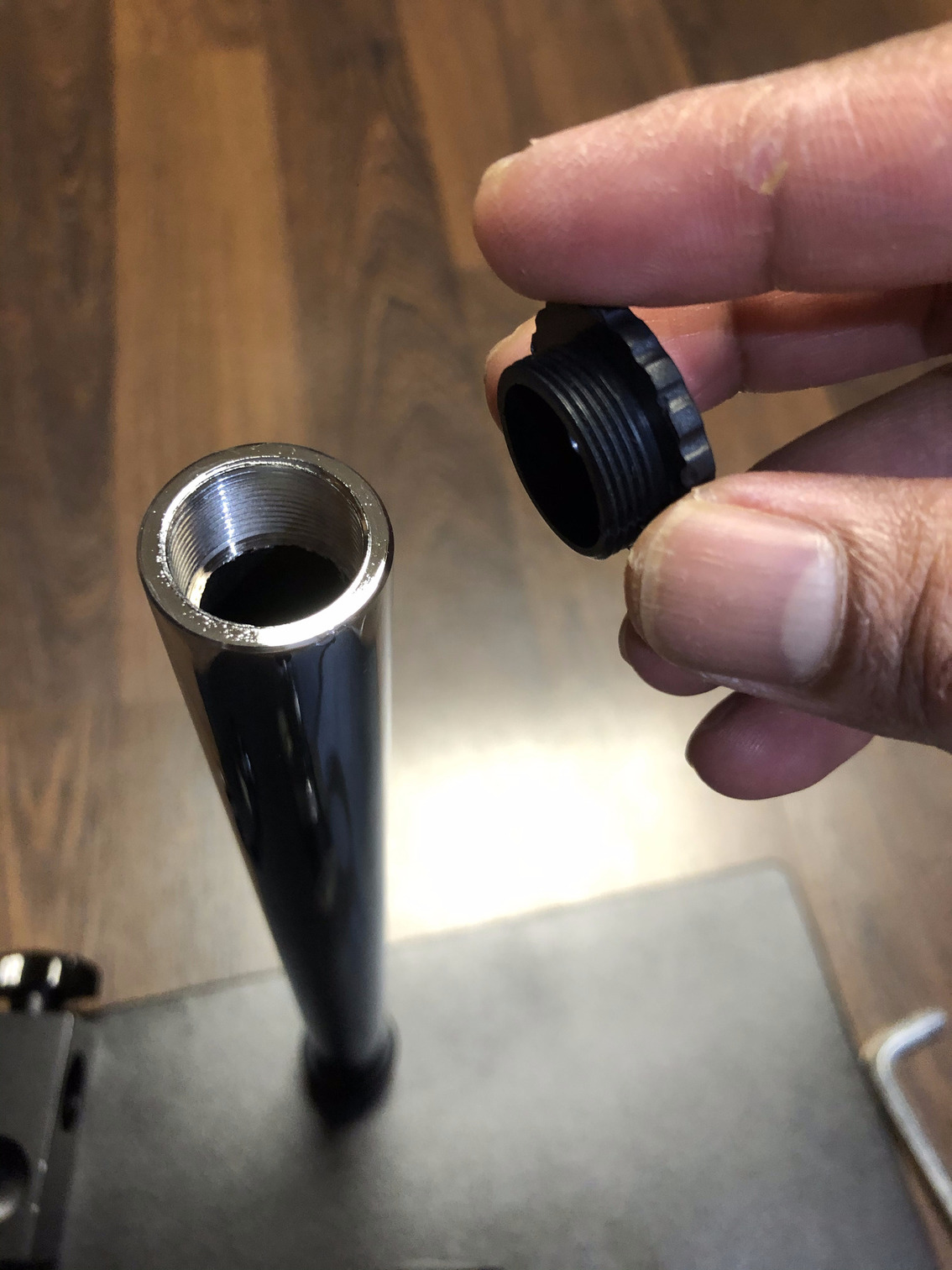
Step 5: Unscrew the top cap on the pillar. It is a metallic cap. There was suprisingly no plastic used in the stand which I think is good design.
Step 6: To hold the side-arm rod two brackets need to be inserted on the main pillar arm as shown in the below images.
First screw in the small bracket at a level, preferably in the middle of the main pillar, where the side-arm is to be fixed.
Next insert the bracket through which the side-arm would pass through and be held along the main pillar.
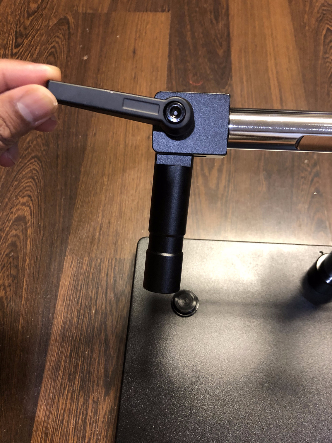
Step 7: Unscrew the cap on the side-arm first.
Step 8: Insert the side-arm left-to-right and screw the cap back on.
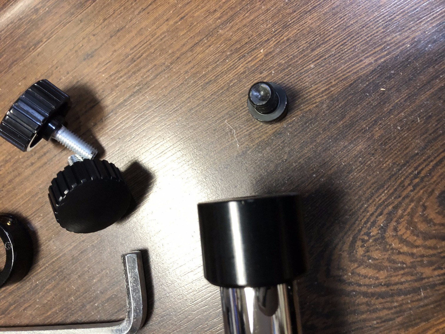
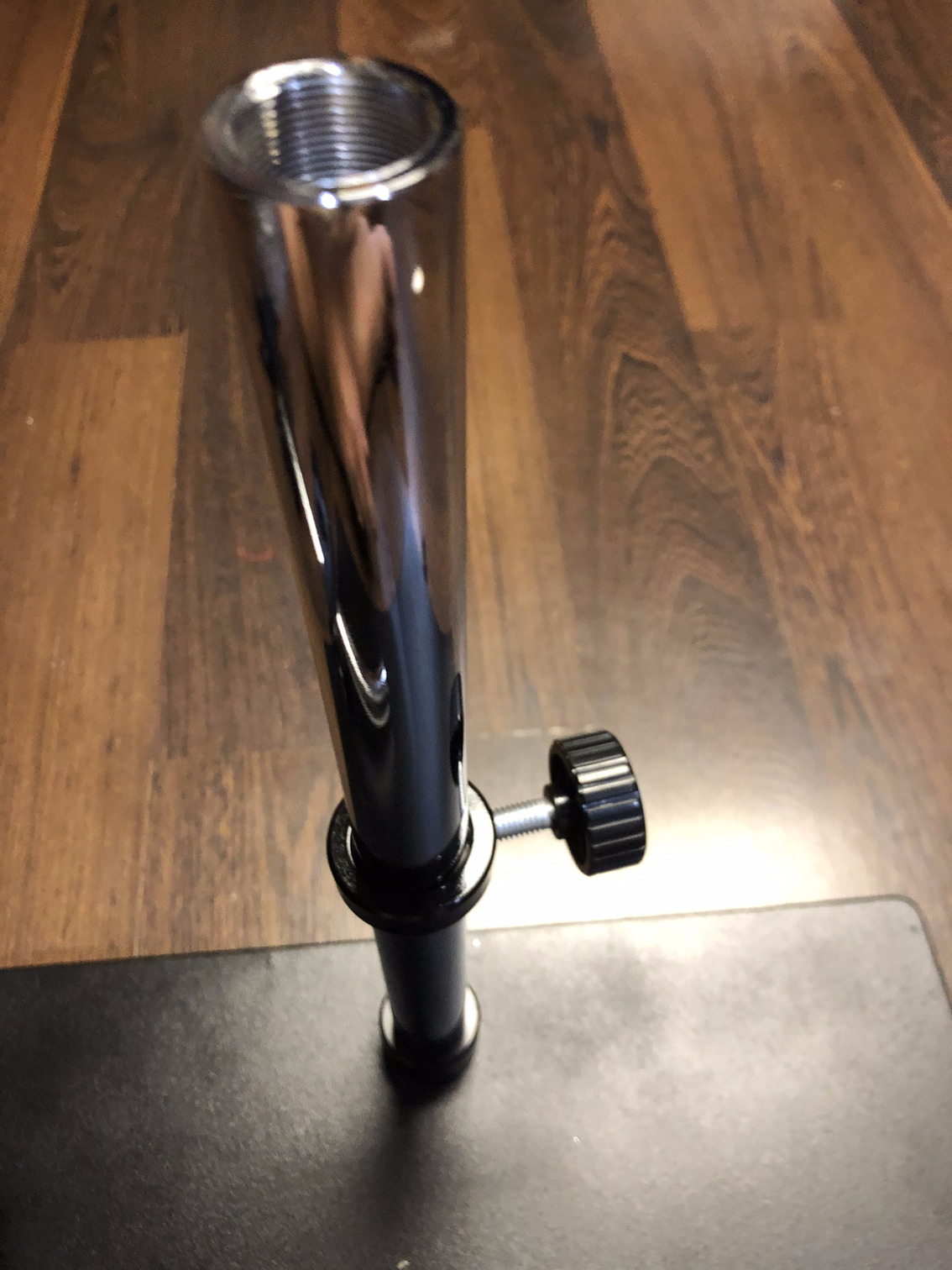
Step 9: Loosen the wing nut on the side-arm pillar using your hand. Next, take off the metallic cap. This is where the microscope bracket fits in.
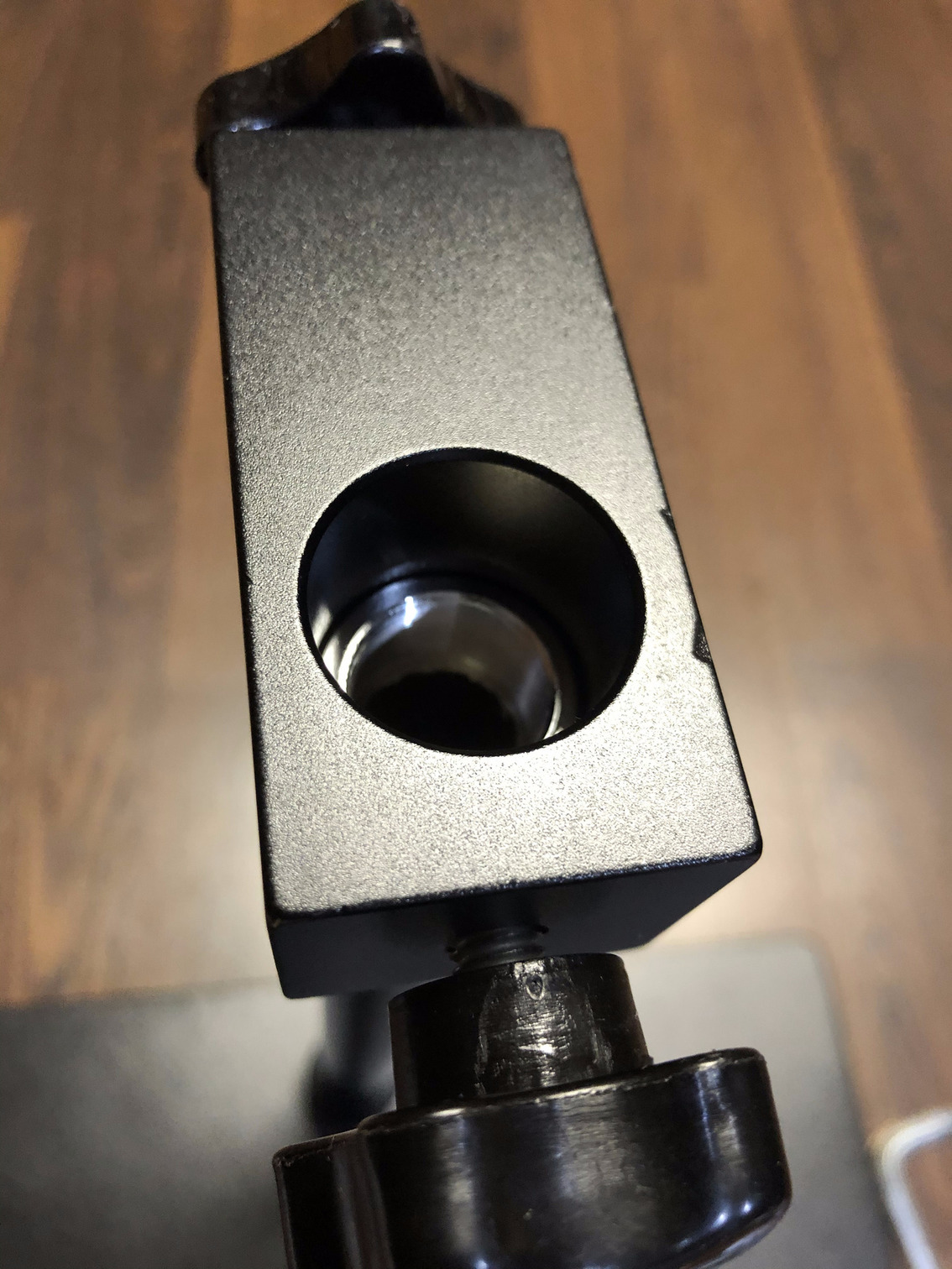
Step 10: Insert the microscope holding bracket into the side-arm end and tighten the knob behind the bracket. This bracket will have to be inserted vertically first and the metallic cap has to be screwed back in.
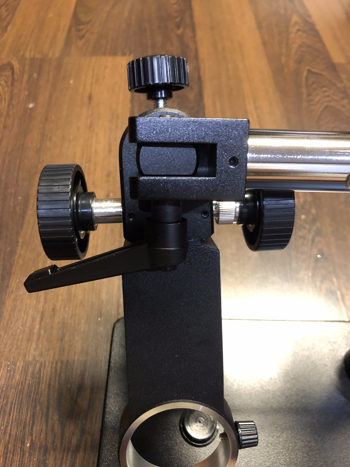
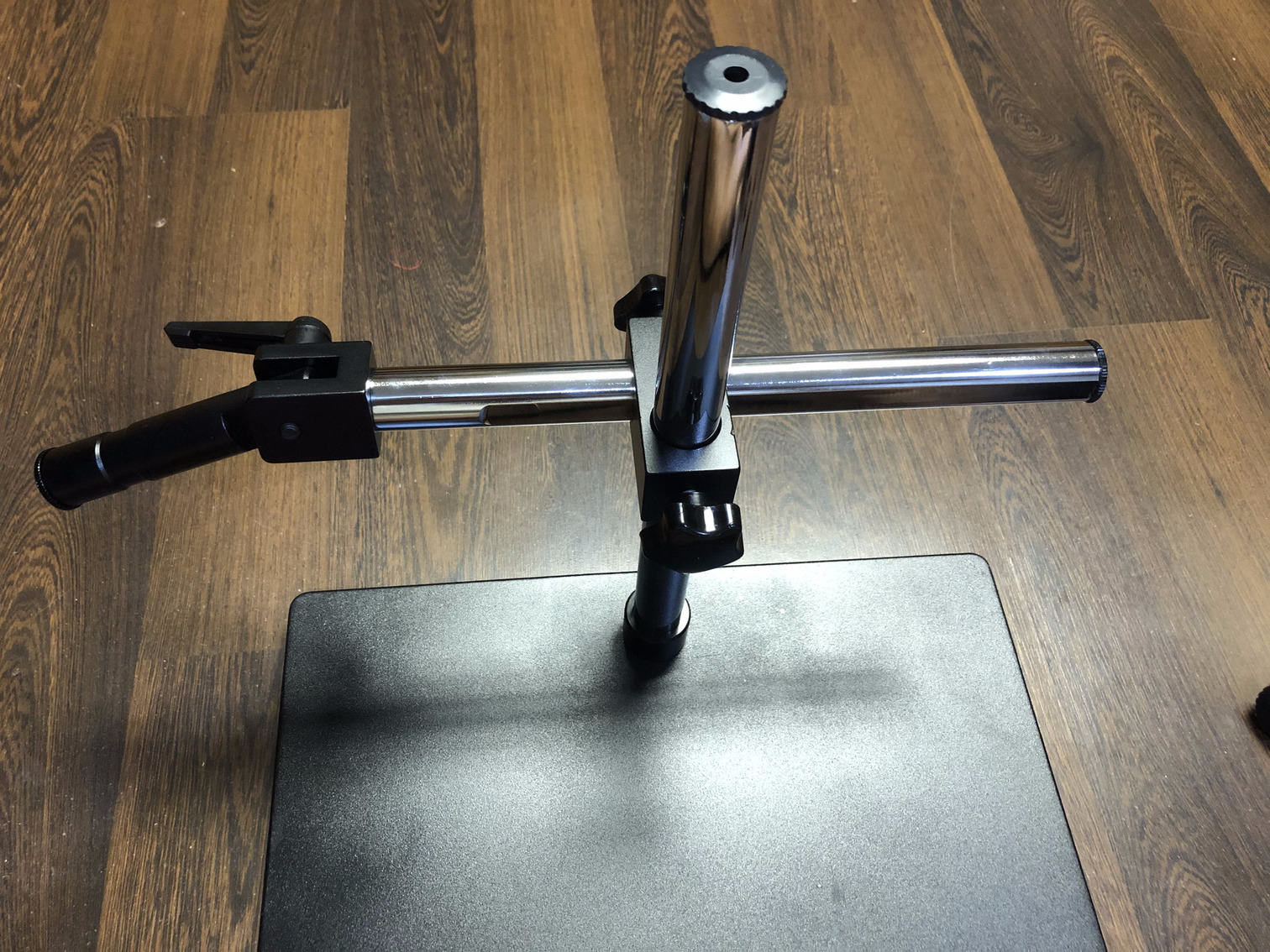
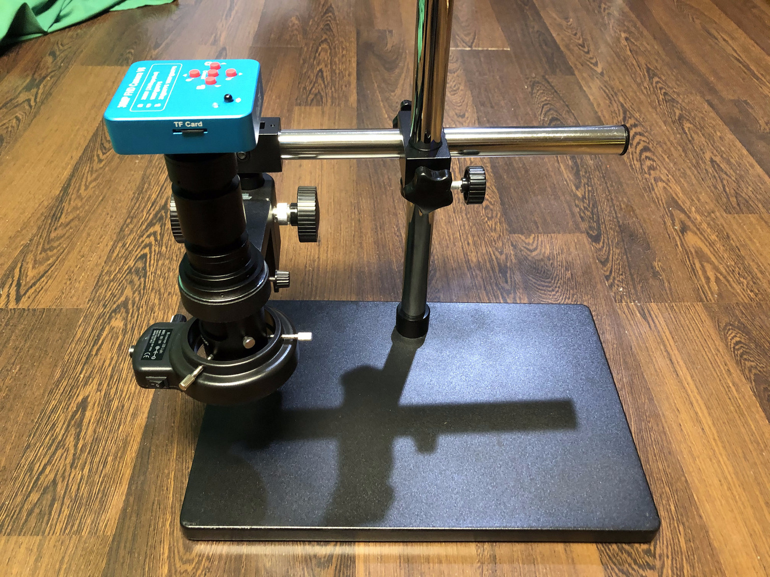
Step 11: Then using the wing nut turn it sideways so that it looks like below, ready to hold a microscope in.
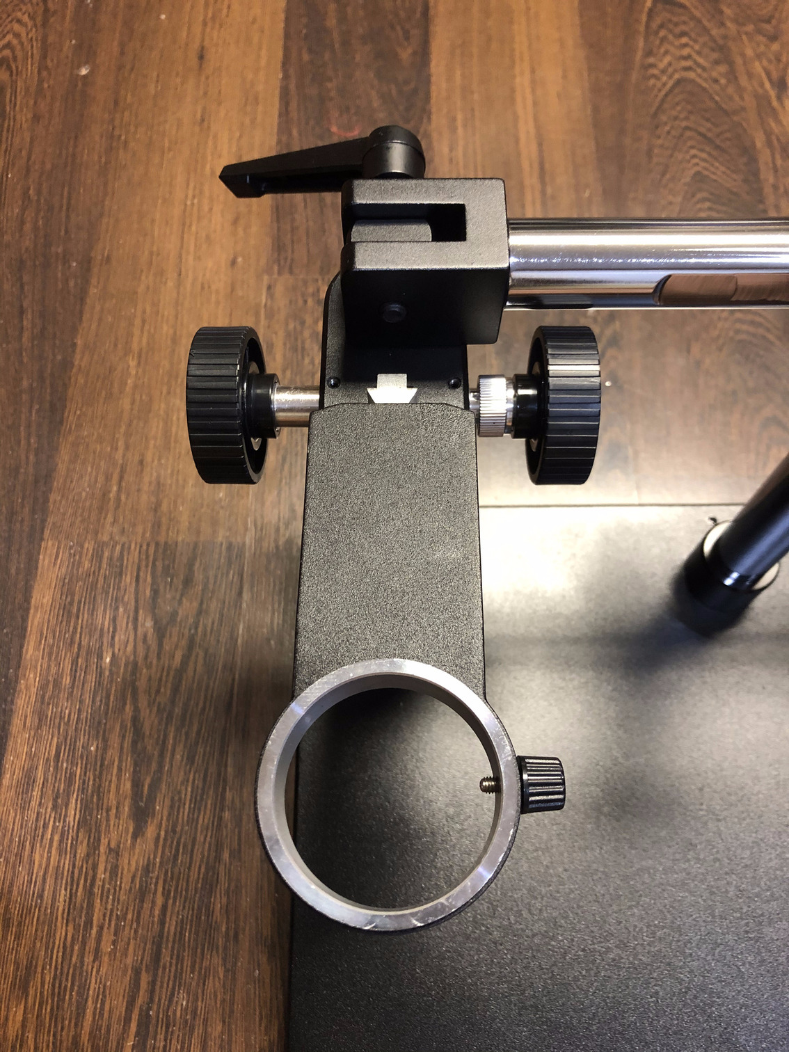
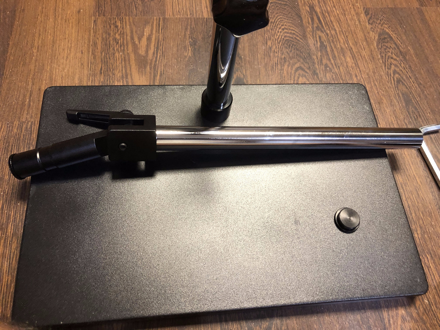
Step 12: The stand is now fully assembled and ready for use. Tighten all the nuts using the supplied hex key.
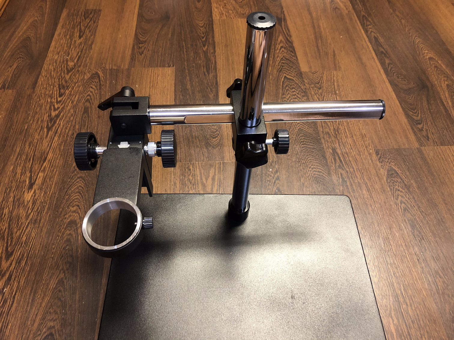
The control knobs on each of the main pillar and side-arm pillars can be used to raise and lower the microscope based on requirements or better visuals.
Setting Up the Microscope
The microscope does not need any assembly but needs to be attached to the stand in a certain order to make sure it works and moves correctly along with the control knobs on the stand. Below is the quickest way to do this right the first time. It took me a couple of tries to figure out how to let it stay in position. The step numbering continues from the previous section.
Step 13: The microscope comes with a lot of components as seen in the next two images (packed and unpacked): a blue microscope camera, a microscope, a 1X magnifying lens, a 2X magnifying lens, an LED light attachment with a switch, a remote control for the camera, a power cable for the camera, a power cable for the LED light attachment, an HDMI cable, a USB cable and a 16GB micro-SD card for the camera. There is a CD with drivers for connecting the camera to a Microsoft® Windows computer via the supplied USB cable. The manual that’s visible in the Step 13b image is for the camera and its remote control, and not for the setup with a stand. Open up the package to make sure all these components are present.
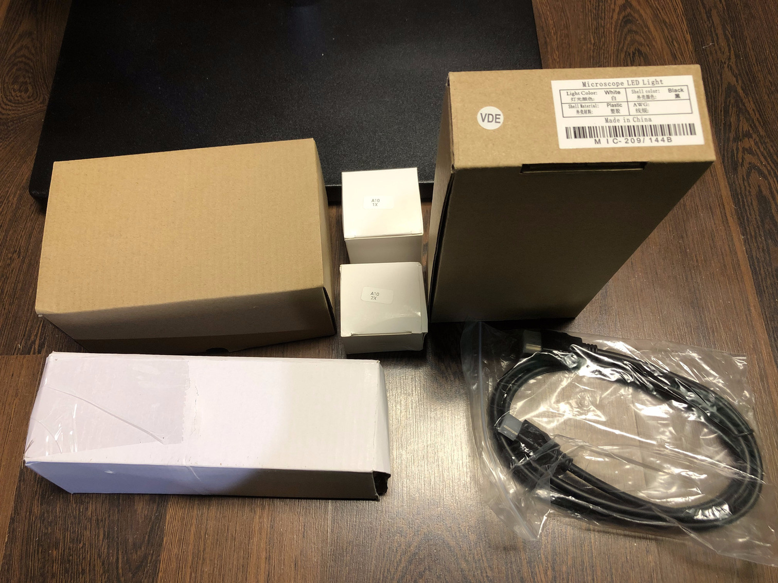 Step 13a. Packed contents
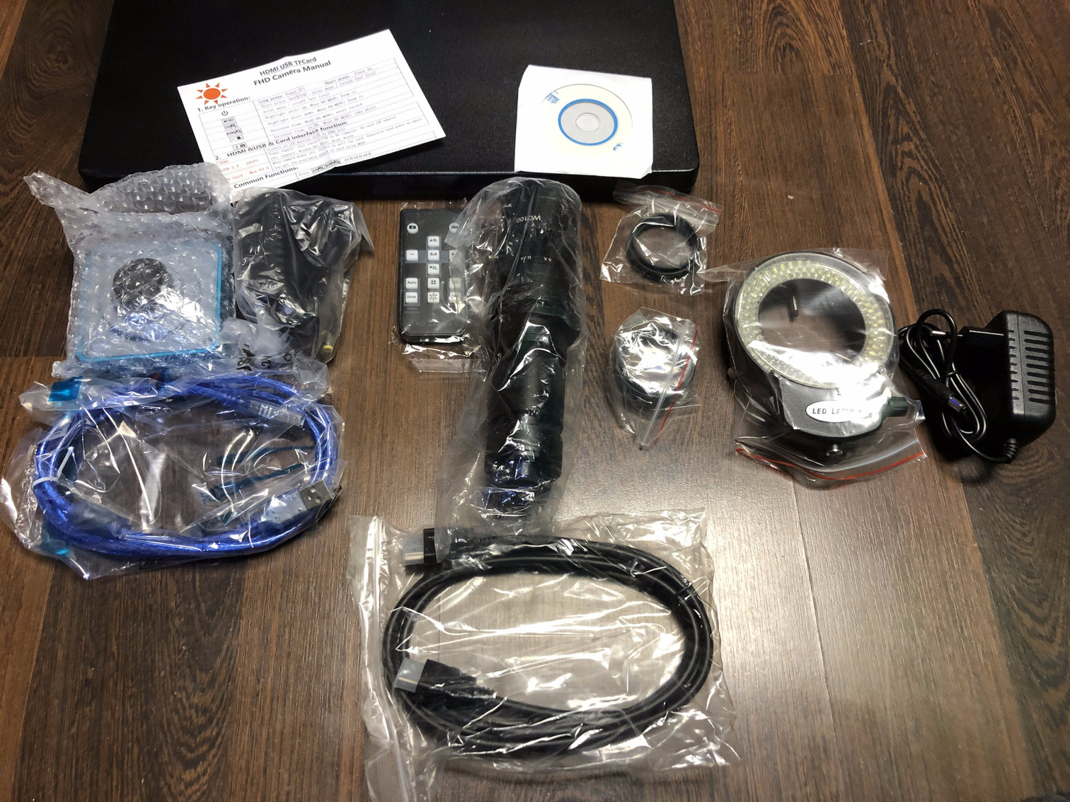 Step 13b. Unpacked contents
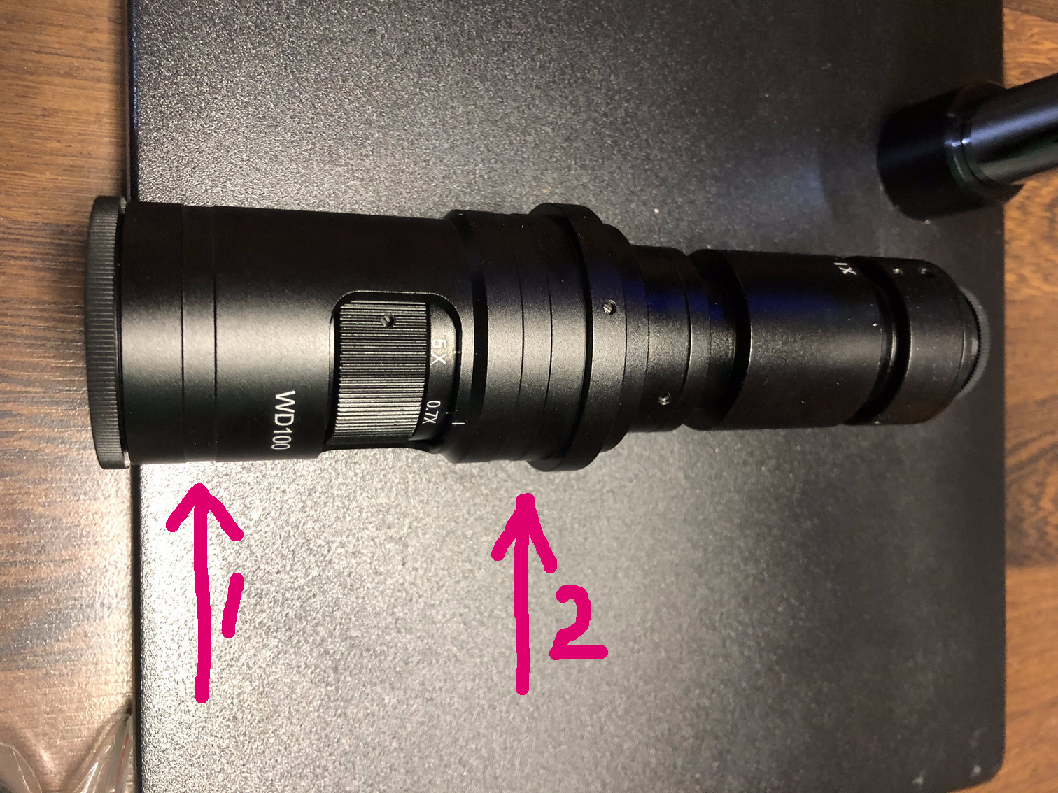
Step 14: Locate the 2 bands, as shown by the magenta arrows, where the LED light attachment (arrow 1) and the microscope holding bracket (arrow 2) from Step 10 in the previous section will be attached.
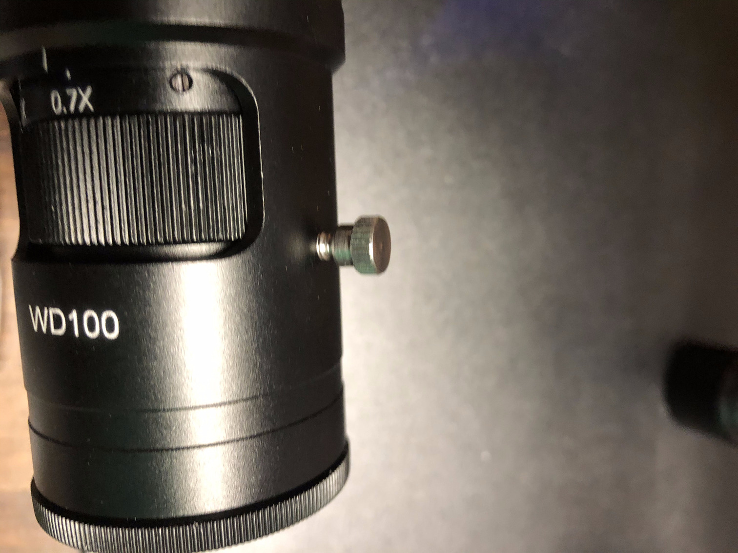
Step 15: Unscrew the screw as shown in the image below that’s next to the magnifier regulator knob. This needs to be done to allow the microscope to slide through the gap in the holding bracket on the stand.
Step 16: Carefully insert the microscope through the bracket’s center hole to the level as shown by the arrow 2 in Step 14’s image.
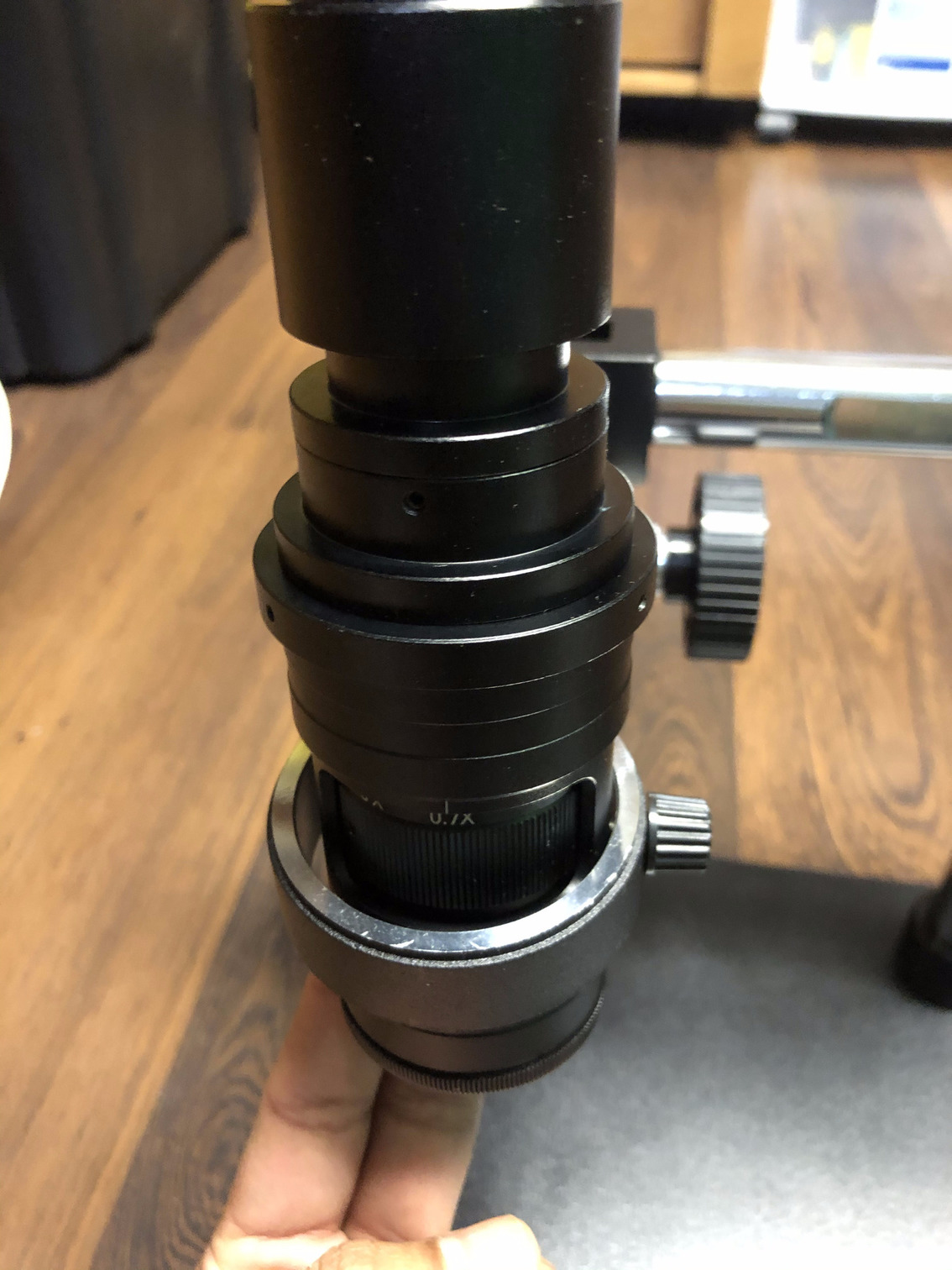
Step 17: Tighten the screw with a plastic cap (seen in the image below) on the bracket onto the scope so it is able to stay in place safely without dropping. Gravity is dangerous for this delicate scope ! Remember to install the steel screw that was removed in Step 15 back in place.
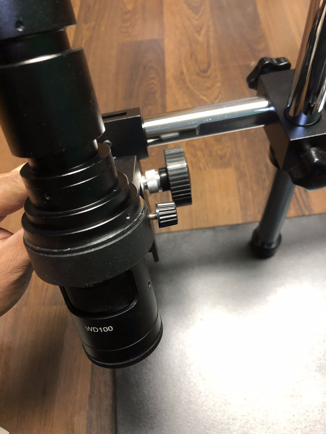
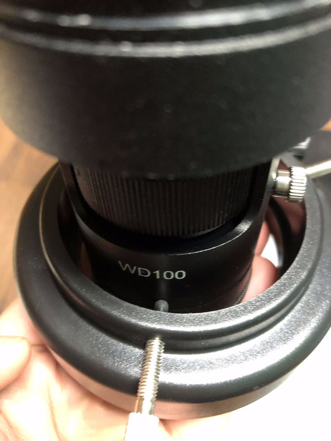
Step 18: Using the three screws on the LED light attachment, screw them in symmetrically on the parallel band below the regulator knob or the WD100 label. Refer to Step 14’s image to understand the location.
Step 19: Unscrew this lens cap at the upper end of the microscope.
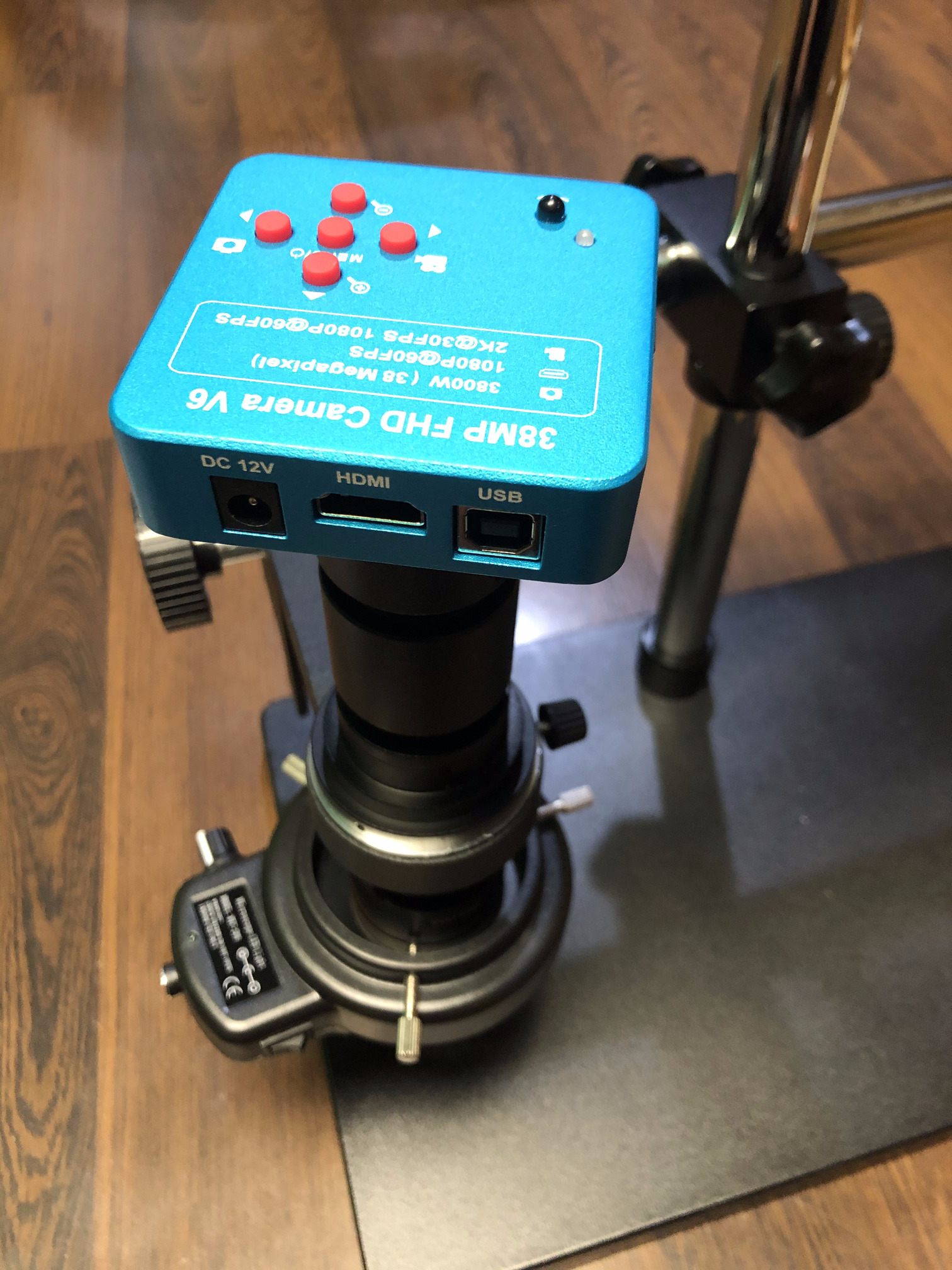
Step 20: Screw in the blue camera onto that end as shown below.
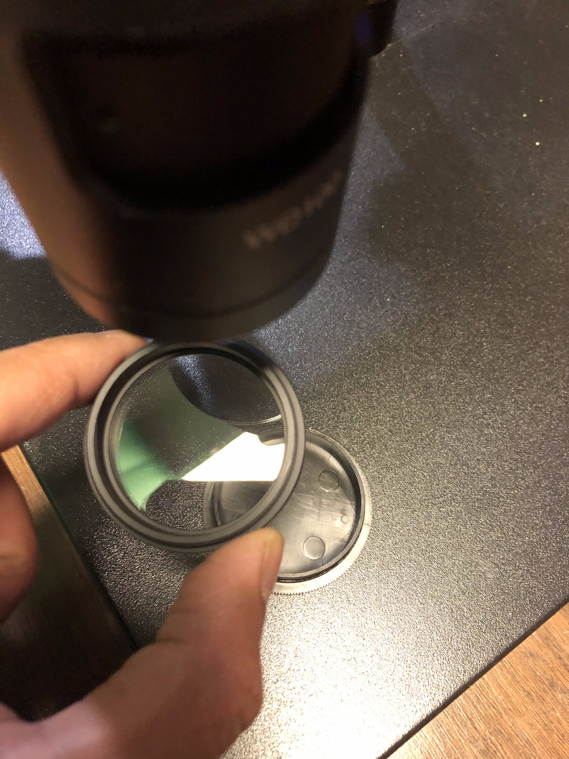
Step 21: Unscrew the lens cap at the lower end of the microscope, and screw in the supplied 1X or 2X lens into the scope based on preference or need for the task. I am using the 1X lens since it seems adequate.
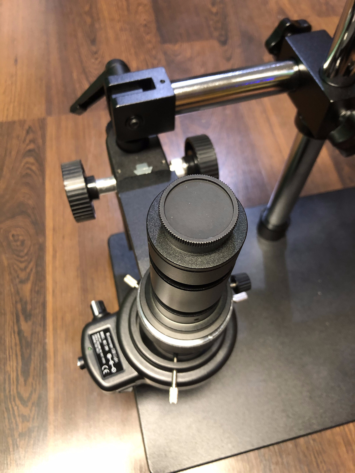
Step 22: The fully setup microscope along with the LED light attachment should look like this.
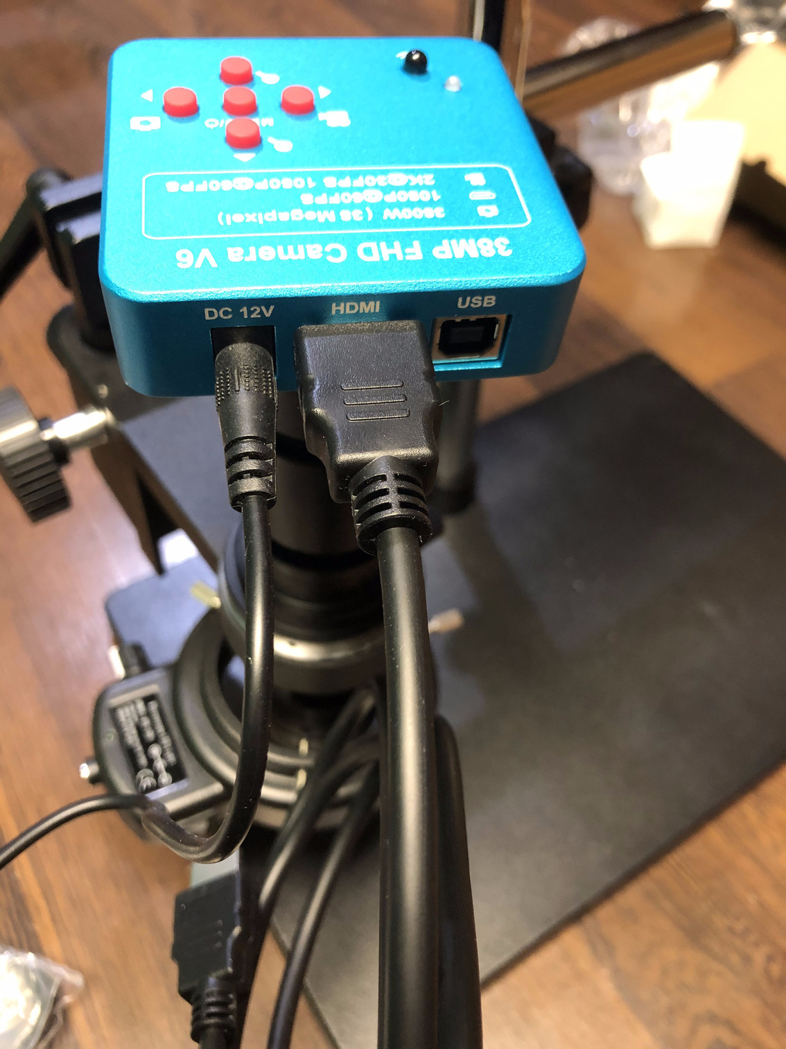
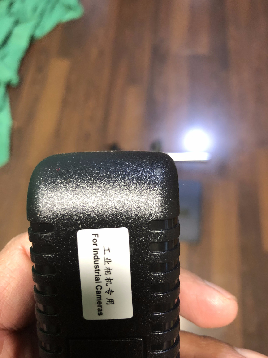
Step 23: Connect the HDMI cable from the camera to the TV or monitor. Connect the respective power supplies to the camera and to the LED light attachment. Step 24 describes these two power supplies which are different from each other.
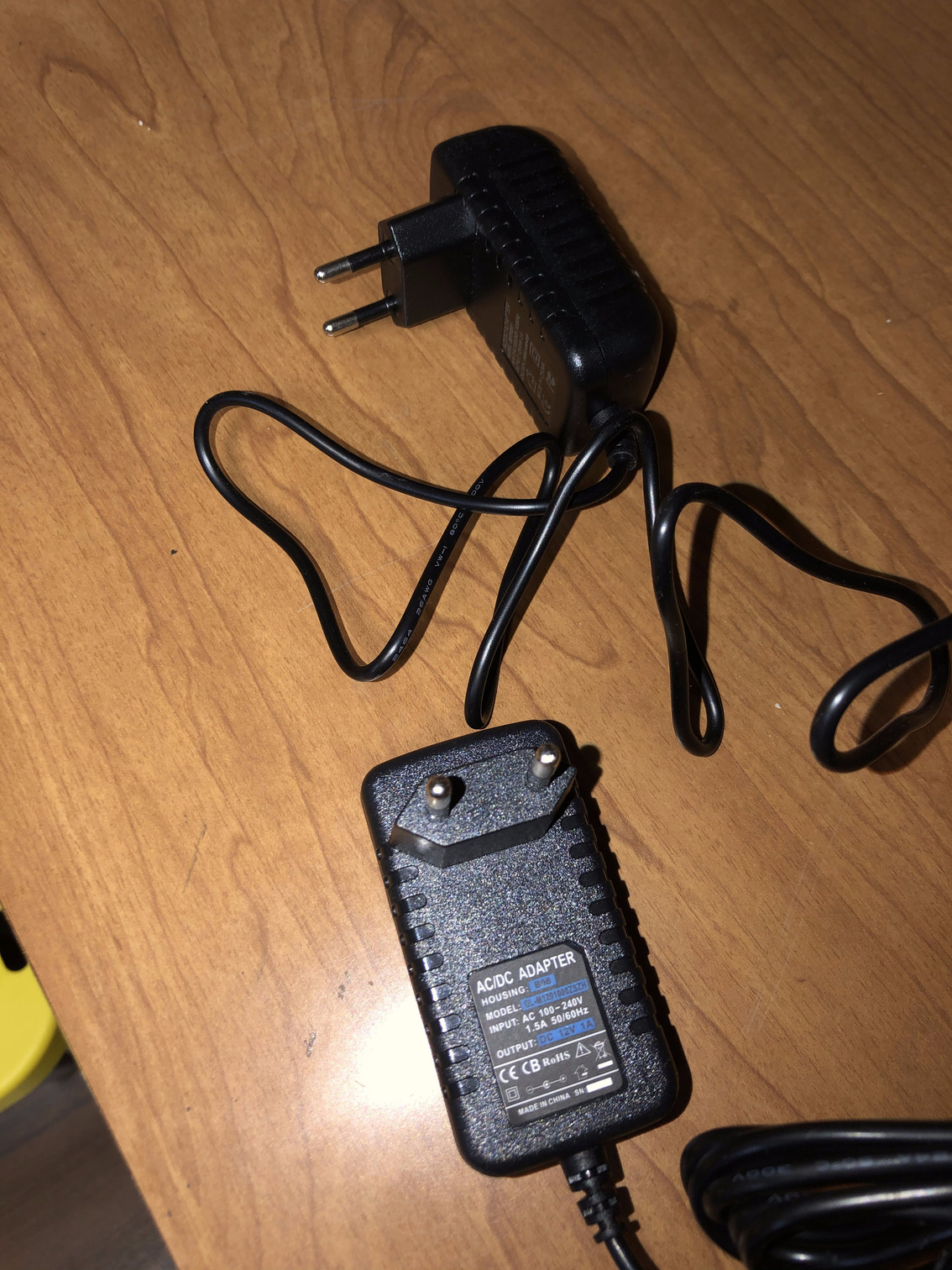
Step 24: The power supplies for both the camera and the LED light attachment are different. Both came with EU plugs, and I had to purchase a cheap $6 EU-to-US 2-pin adapter from Amazon which served its purpose perfectly. Once these adapters have been procured, connect the power supplies to a surge protector and start using the microscope.
 Step 24a. The EU plugs that come with the microscope
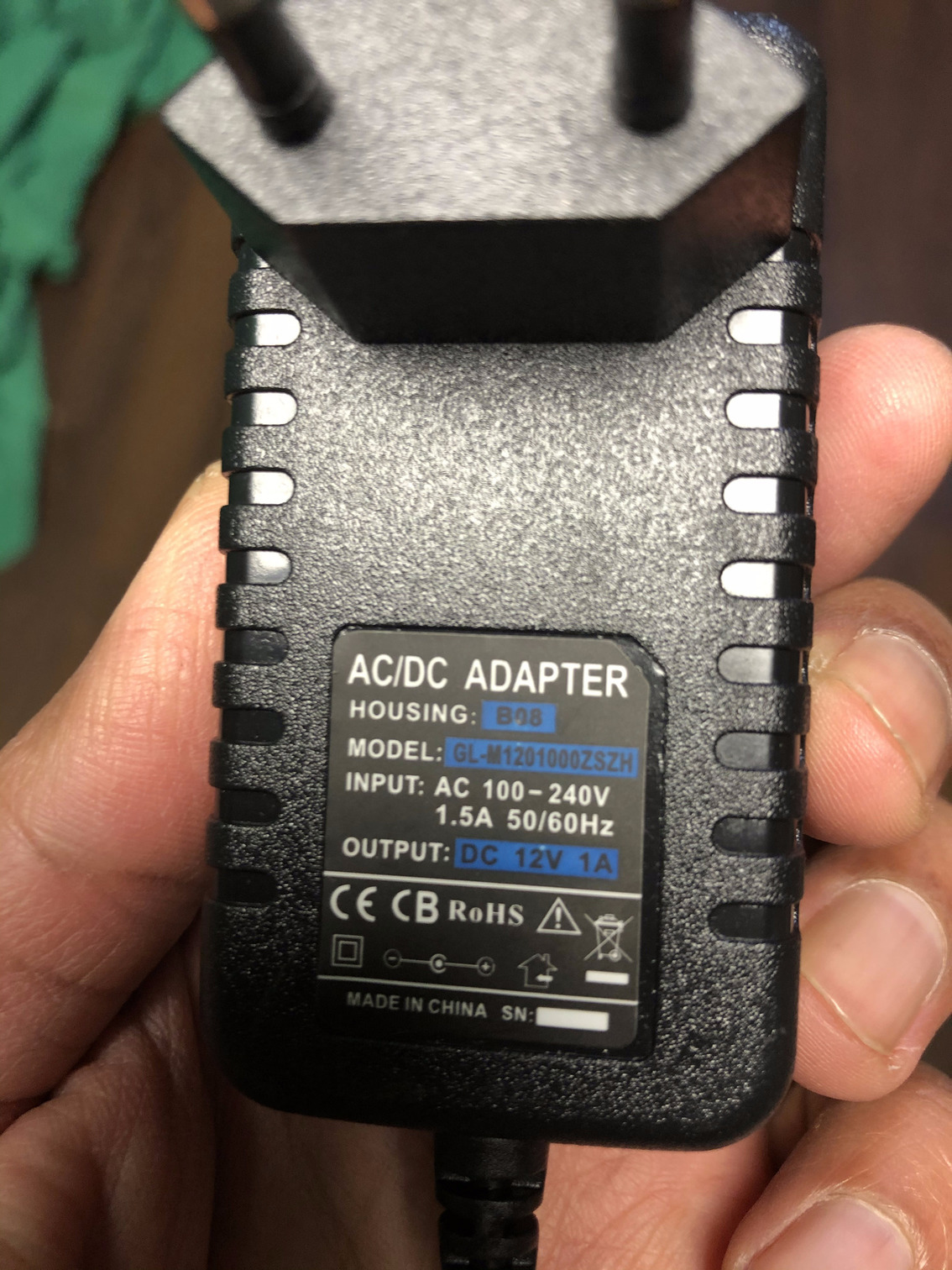
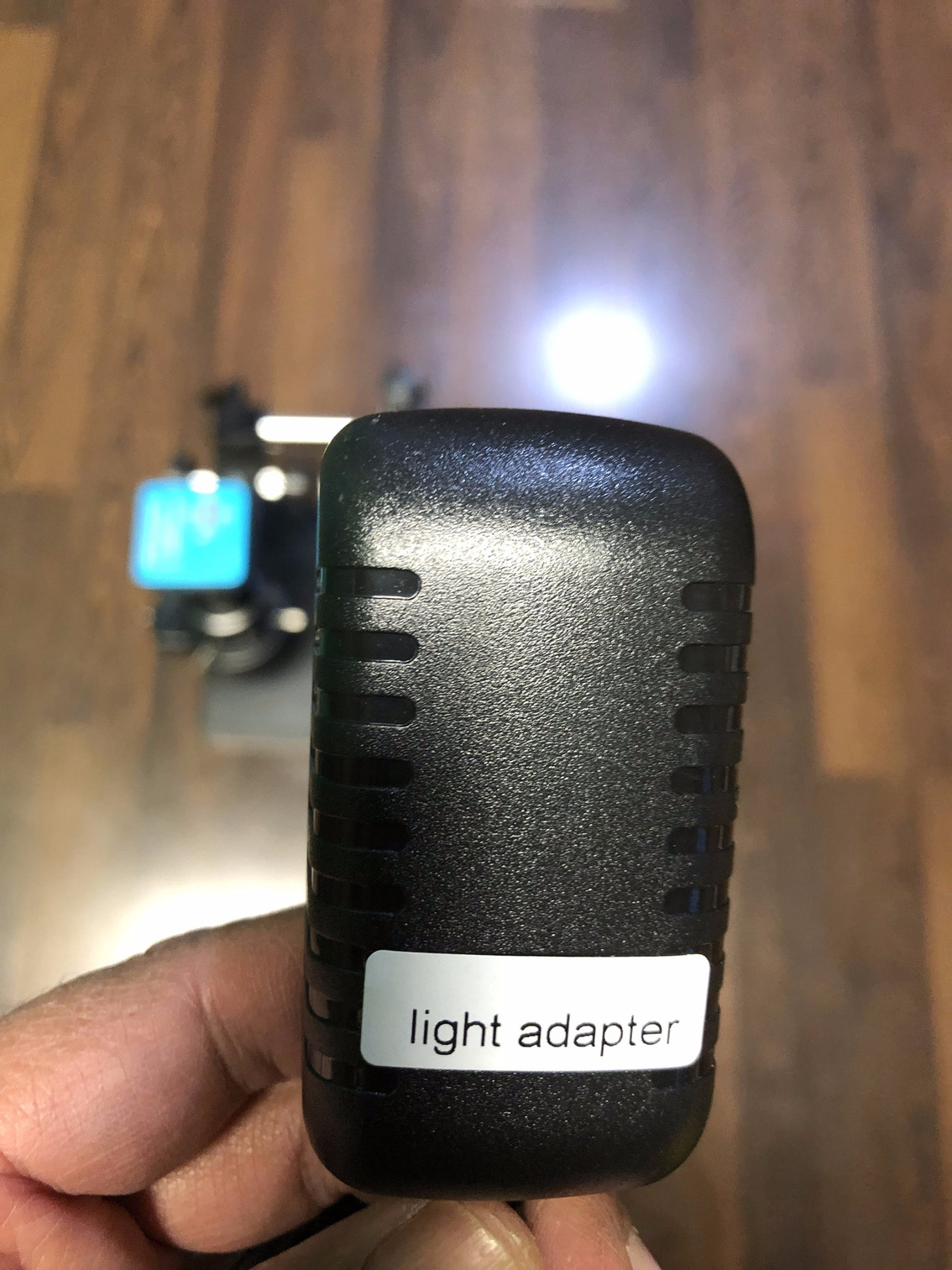 Step 24b. The light power supply is labeled
 Step 24c. The light power supply has a 12V 1A output
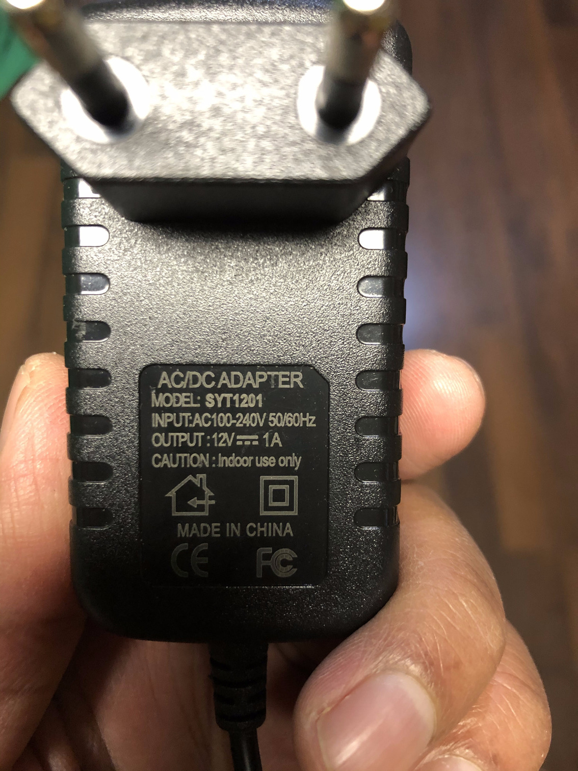
 Step 24d. The camera power supply is labeled
 Step 24e. The camera power supply has a 12V 1A output but has a 1.5A input (slightly different from Step 24d)
The next section shows how well the microscope worked for me.
Using the Microscope
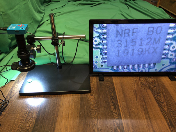
I am spending some of my free time learning antenna design, and as part of my pursuit to re-use electronic devices to do something they have not been designed for, I decided to disassemble a Disney World bracelet with FCC ID Q3E-MB-R1G2. The designers have done a fantastic job with the antenna which is the spiral looking wiring, near the edge of the board, in the tiny quarter-sized board as seen in Figure i. Place the board below the microscope lens as in Figure ii and after some adjustment, Figure iii shows how clear the name of the chip is visible. The microscope makes it incredibly easy to see all the connections and the name of the chip and any other low level details that can be visible. Despite the fact that these microscopes are sold for phone repair, they can be used for any form of reverse engineering or other electronics repair.
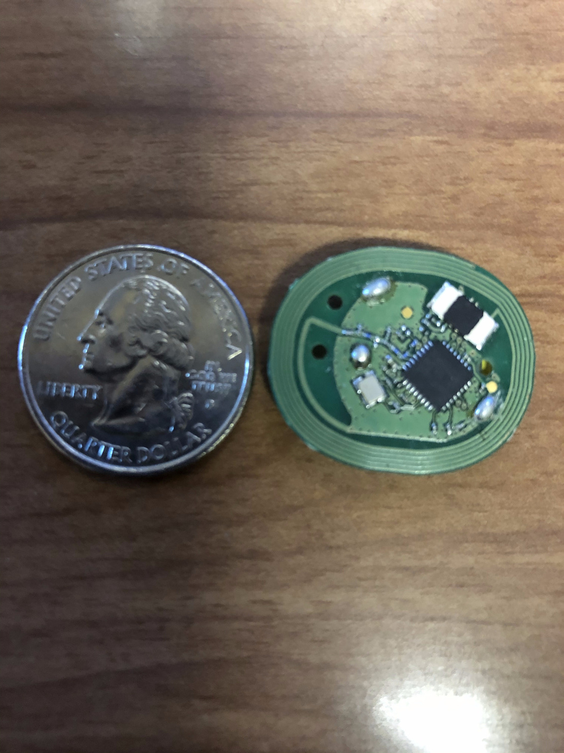 Figure i. Perspective view of the size of the circuit board with a USD 0.25 coin
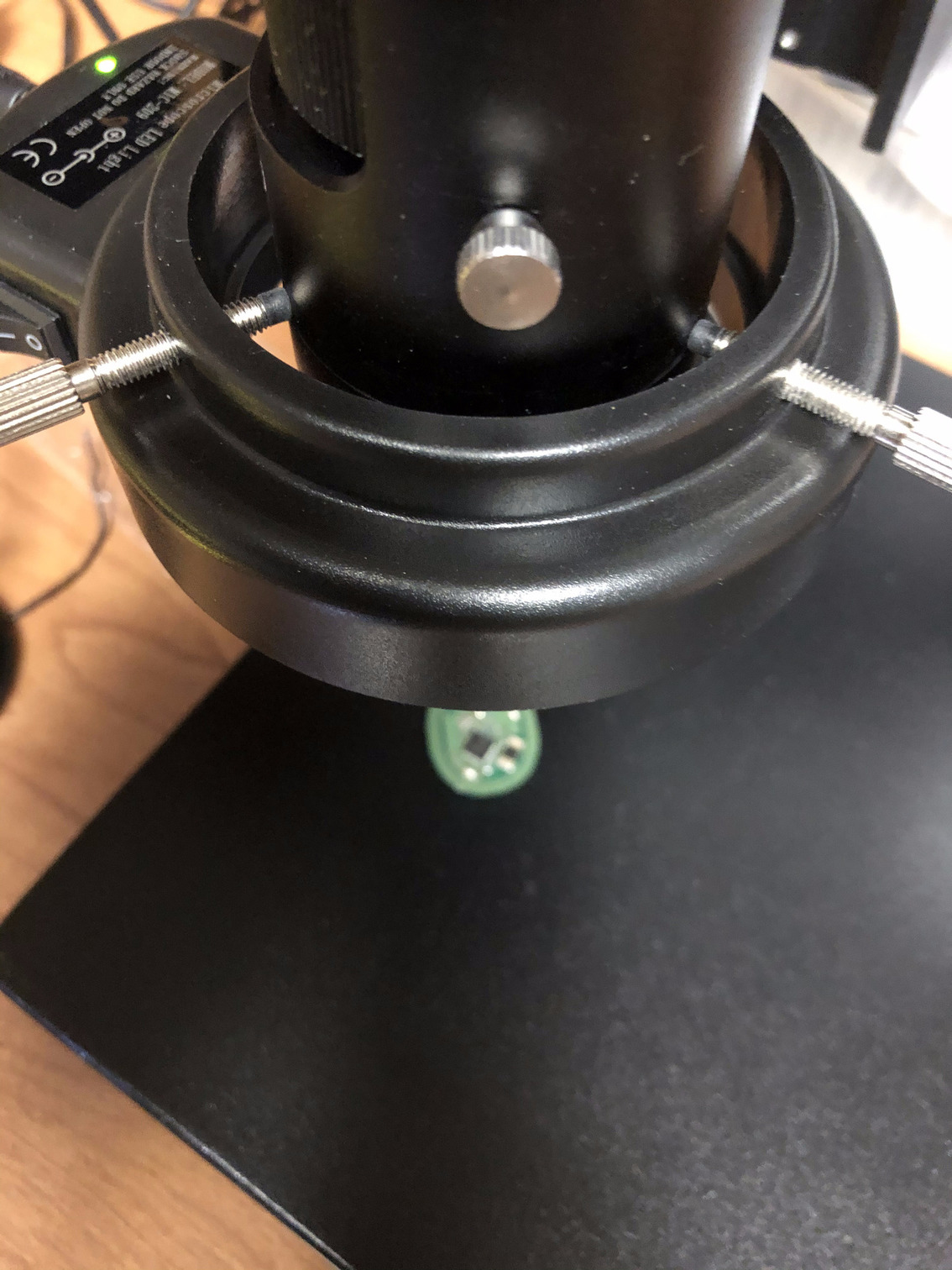 Figure ii. Place the circuit board under the lens
 Figure iii. Enlarged view of the main processor
The microscope camera comes with buttons to allow the user to save images or videos, transmit them live to a computer via a USB cable (provided) and even comes with a remote control. Pressing the photo save button saves the image on the screen to the microSD card present in the camera. I have not tried the USB cable way to save it directly to a computer.
The remote control may come in handy if the user is making a video or experience failure of the actual buttons themselves. I have not found a real use case for it.
The green screen behind the microscope in Figure iii is a work-in-progress as I am setting up a green screen to be able to make some videos related to my research soon. Crossing my fingers as I have too many projects and not enough time to complete them.
Vendor Specification Images
I saved the microscope specification images for archival purposes, in case I may need it. These pictures helped me setup the microscope into the stand correctly.
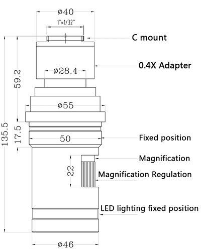 Figure a. Microscope body specification diagram
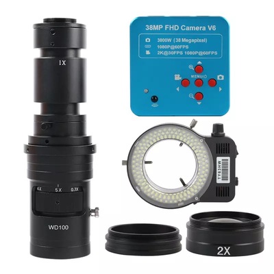 Figure b. Parts supplied in the package
 Figure c. Microscope camera side view with vendor logo
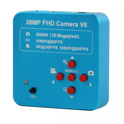 Figure d. Microscope camera top view of control buttons
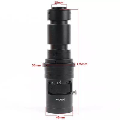 Figure e. Microscope body with measurements
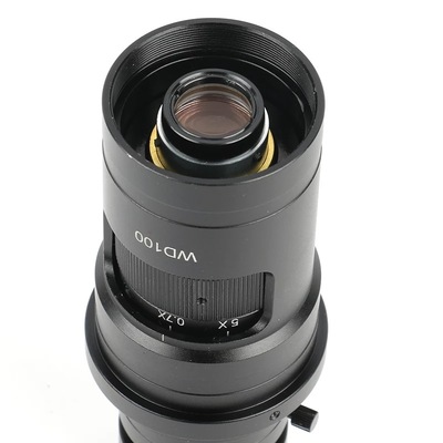 Figure f. Microscope bottom lens location
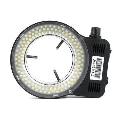 Figure g. LED light attachment side-view
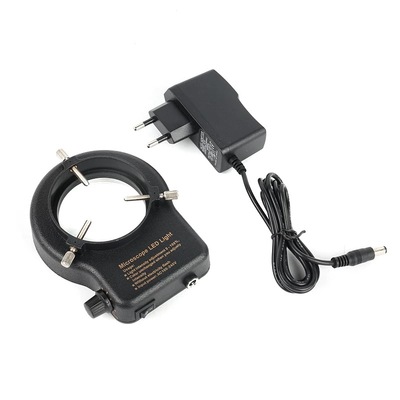 Figure h. LED light attachment with power cable
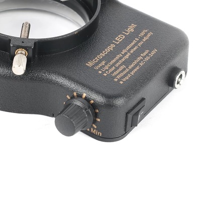 Figure i. LED light attachment switch and intensity controller
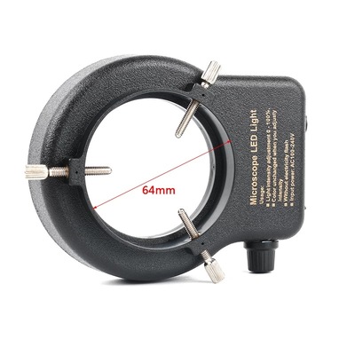 Figure j. LED light attachment measurement of center hole
 Donate BITCOIN to 19hrWWw1dPvBE1wVPfCnH8LqnUwsT3NsHW.